
How precision metal fabrication reduces fit-up issues in assemblies
Author
Date Published
Reading Time
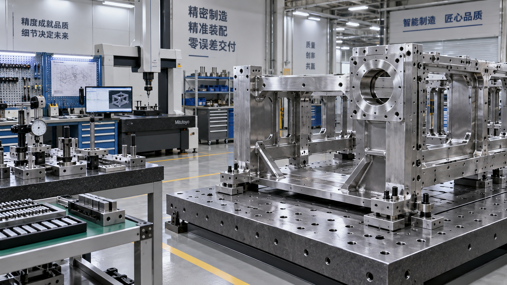
A steel frame is ready, mechanical equipment has arrived, and installation crews are waiting. Then the first bracket will not sit flush against its mating surface. A bolt pattern is slightly off. A duct transition twists under load because two sections that looked correct on separate drawings do not meet correctly in the field.
These are fit-up issues: small dimensional, geometric, or interface mismatches that become highly visible when fabricated parts must work together as an assembly. They are rarely “small” from a project perspective. A few millimeters of variation can trigger site modifications, delayed inspections, extra lifting operations, material waste, and uncomfortable conversations about who owns the rework.
For project managers and engineering leads, precision metal fabrication is not simply a higher-grade purchasing option. Used appropriately, it is a method of reducing uncertainty at the points where components, trades, and schedules intersect. Better control of dimensions, hole locations, flatness, weld distortion, and reference datums gives assemblies a greater chance of fitting as intended before they reach the project site.
The value is especially clear in modular skids, machinery frames, architectural metalwork, process piping supports, enclosures, structural subassemblies, transport equipment, and retrofit work—anywhere a fabricated part must connect to equipment, existing structures, or parts made by another supplier.
Fit-up failures usually begin long before installation
Field teams often discover the problem, but they do not always create it. Fit-up trouble commonly begins during design release, supplier handoff, or process planning. A drawing may show nominal dimensions without defining functional tolerances. One vendor may measure from the outside edge of a formed part while another works from a centerline. A weld sequence may pull a frame out of square after critical holes have been machined. Even a correct individual part can fail at assembly level when the tolerance stack across several components becomes too large.
This distinction matters because “make it to drawing” is not enough when the drawing does not communicate how the parts are intended to locate, align, or carry load. A project team needs to understand the functional interfaces: which face establishes position, which holes are locating holes rather than clearance holes, where adjustability is acceptable, and where it is not.
Precision metal fabrication addresses this upstream. It connects design intent with a controlled manufacturing route, rather than treating cutting, forming, machining, welding, finishing, and inspection as unrelated activities. The result is not perfect parts in an abstract sense. It is parts that are consistently suitable for the assembly they are meant to enter.
The assembly is the real unit of quality
A fabricated base plate may appear acceptable on its own, as may the mating equipment frame. But if the mounting pattern, hole perpendicularity, surface flatness, or datum interpretation differs between them, the assembly fails its practical test. Project managers should therefore ask suppliers to evaluate the part in context.
That means reviewing more than the component drawing. Useful input can include mating-part drawings, 3D models, installation orientation, fastener specifications, access restrictions, lifting points, field-weld locations, and the sequence in which the assembly will be built. For a replacement component, an accurate record of the existing condition may be even more important than the original drawing, particularly where prior site changes have occurred.
When suppliers understand the assembly, they can identify details that are easy to overlook: a wrench cannot reach a fastener after adjacent panels are installed; a powder-coated contact surface changes the effective seating condition; a formed return blocks insertion; a heavy weld lies too close to a precision-machined interface. Catching such conflicts before production is much less disruptive than correcting them after delivery.
Control the datums, not just the dimensions
Many fit-up problems are really datum problems. A datum is the reference from which a critical feature is located and inspected. Without clear, shared datums, two parties can produce parts that seem compliant yet do not align in practice.
Consider a welded equipment frame with four mounting holes. If the holes are located from edges that can vary due to cutting and welding, the frame may drift away from the intended coordinate system. If the functional mounting surface and a primary machined feature are established as inspection datums instead, the supplier has a more reliable basis for holding the relationships that matter.
For assemblies with multiple interfaces, the drawing package should make clear:
- the primary, secondary, and tertiary locating surfaces or axes;
- which dimensions are critical to assembly function;
- the permissible position variation for holes, slots, pins, and cutouts;
- flatness, parallelism, perpendicularity, or profile requirements where relevant;
- whether dimensions apply before or after welding, coating, galvanizing, or machining.
Not every fabrication needs an extensive geometric tolerancing scheme. Over-specifying ordinary features can add cost without improving installation. The goal is to apply meaningful controls to the few relationships that govern fit, movement, sealing, alignment, or load transfer.
Where precision metal fabrication makes the biggest difference
The term covers a broad set of capabilities, from CNC laser cutting and press brake forming to machining, robotic welding, fixture-based assembly, and dimensional inspection. The most suitable process depends on the part and its functional risk.
For sheet metal enclosures, precise blank development and repeatable bending are often central. Bend allowance, bend radius, grain direction, and springback influence whether doors close, panels overlap, and fasteners line up. A slight inconsistency at each bend can accumulate across a long cabinet or multi-panel assembly.
For welded frames and structural modules, the main concern may be distortion. Heat input can alter straightness, squareness, and hole position, especially on thinner sections or long members. A capable fabrication plan may use purpose-built fixtures, balanced weld sequencing, intermittent welds where structurally appropriate, staged measurement, stress-relief considerations, or post-weld machining of critical faces.
For machined-and-fabricated assemblies, sequence becomes decisive. It is often risky to machine precision features before substantial welding if later heat distortion can move them. In other cases, pre-machining is necessary to create accurate locating features for a welding fixture. There is no universal sequence; the correct answer comes from understanding what must remain true when the final assembly is installed.
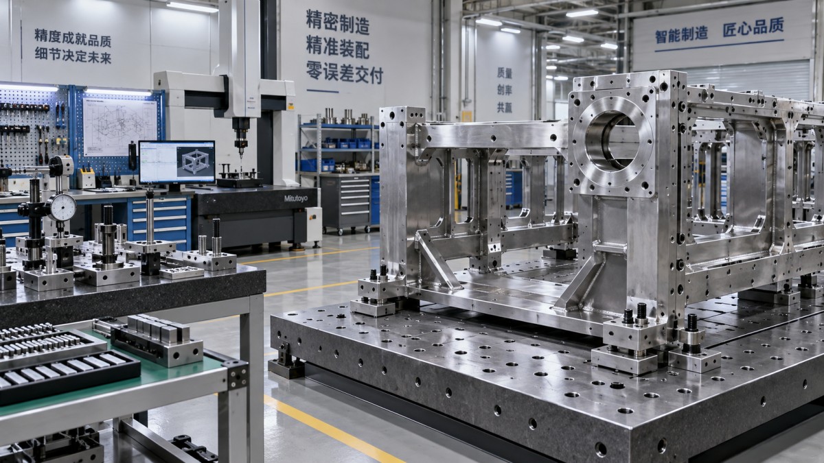
Repeatability matters as much as a single good first article. A manually adjusted setup may produce one component that fits, then drift across a production batch. CNC programs, documented work instructions, controlled tooling, inspection checkpoints, and traceable revisions reduce that variation. This is particularly important when a project requires phased deliveries or replacement parts months after the original build.
Tolerance stacking: the quiet source of site rework
Project teams sometimes focus on the tolerance of one part while overlooking the combined variation of the full assembly. This is tolerance stacking. If a mounting plate, bracket, frame, cover, and installed equipment all have permissible variation in the same direction, their accumulated offset can exceed the available clearance.
Imagine a cover panel designed to align with a row of brackets. Each part may fall within its specified limits, but the combined result may leave too little space for assembly. The team then responds with enlarged holes, shims, forceful alignment, or site drilling. These remedies may be workable in a non-critical application, but they can compromise appearance, corrosion protection, fatigue performance, weather sealing, or future serviceability.
A practical tolerance review does not require turning every project into a theoretical exercise. It requires identifying closed-loop dimensions—the chains of features that must meet without adjustment—and examining their worst-case or statistical accumulation where the risk justifies it. Long assemblies, tight clearances, repeated modules, and equipment interfaces deserve particular attention.
Sometimes the best response is not tighter tolerances everywhere. It may be to add controlled adjustment in a non-critical location, use slotted holes in the correct direction, introduce a shim range, redesign a locating feature, or establish one component as the master reference. The important point is that adjustability should be designed intentionally, not improvised on site.
Supplier involvement should start before the purchase order
Late supplier engagement often turns fabrication into a quoting exercise: a drawing is sent, a price is returned, and manufacturing begins after award. That workflow can work for uncomplicated commodity parts. It is less dependable for assemblies with meaningful fit-up risk.
Early fabrication review gives the supplier an opportunity to assess whether the specified tolerances can be achieved consistently with the selected material and process. They may flag a narrow flange that will distort during welding, an internal corner inaccessible to tooling, a bend sequence that creates interference, or inspection criteria that cannot be verified after coating. These questions are not obstacles to progress; they are often the last low-cost opportunity to prevent expensive field changes.
A productive review should include the engineer responsible for design intent, the project manager responsible for cost and schedule, and the fabrication contact responsible for process feasibility. Where installation is complex, involving a field superintendent or assembly technician can be equally valuable. They may recognize a real-world constraint that is invisible in a model.
Information that improves fabrication outcomes
A strong request-for-quotation package does more than attach a PDF. It tells the supplier which requirements are important and why. Along with controlled drawings and, where available, native or neutral 3D files, consider providing an interface matrix that identifies mating components, responsible parties, critical dimensions, finish requirements, delivery sequence, and any need for trial assembly.
For higher-risk work, ask how the supplier plans to manage the following:
- material identity, thickness variation, and traceability where required;
- fixture design and part location during welding or assembly;
- distortion control and the timing of any post-weld machining;
- first-article inspection and measurement reporting for critical features;
- revision control when drawings or models change during the project;
- packaging and transport protection for precision surfaces, flanges, and alignment features.
The answers reveal more than technical capability. They show whether the supplier is thinking about the delivered, installable assembly rather than only the fabricated item leaving the shop.
Inspection should match the failure mode
Inspection reports can create a false sense of security when they record dimensions that do not govern fit. Measuring overall length may be useful, but it does little to prevent a failed installation if the actual risk lies in hole position relative to a machined face or in the twist of a welded frame.
Effective quality planning begins with a simple question: “How would this part fail during assembly?” The inspection method should then target that failure mode. Hole patterns may require coordinate measurement against defined datums. A sealing flange may need flatness verification. A long welded support may need checks for bow, twist, and diagonal squareness. Complex parts can benefit from a dedicated checking fixture or a trial fit with a representative mating component.
For projects with several suppliers, consider a shared measurement convention. Mixed units, inconsistent revision status, and different coordinate origins are routine sources of confusion. A dimensional report only has value when all parties understand what was measured, from where, with which equipment, and against which revision.
Do not confuse “tight” with “better”
Precision has a cost. Very tight requirements may require slower machining, more specialized tooling, additional inspection, controlled handling, or post-process operations. Those costs are justified when dimensional variation affects safety, function, interchangeability, sealing, or installation time. They are harder to justify on cosmetic or non-functional features.
Project managers are often under pressure to reduce procurement cost, but the lowest unit price can be misleading when it transfers alignment work to the field. At the same time, demanding maximum precision on every feature may consume budget and extend lead times without reducing meaningful risk. The best specification is selective: strict where interfaces demand it, practical where the design has room to absorb normal process variation.
This also calls for honest decisions about field adjustment. In some structures, controlled shimming or slotted connections are sensible and maintainable. In a modular electrical enclosure, precision location may be preferable because later adjustment would disrupt panel alignment, sealing, and access. The correct balance depends on the assembly’s function and the cost of intervention after delivery.
A project-stage checklist for fewer fit-up surprises
Before release to fabrication, project leaders can use a short set of questions to expose avoidable risk:
- What must physically mate? Identify every critical part-to-part, part-to-equipment, and part-to-site interface.
- Which features locate the assembly? Define functional datums rather than relying on convenient outside edges.
- Where can variation accumulate? Review tolerance chains, bend effects, weld distortion, coatings, and installation clearances.
- Is the manufacturing sequence compatible with the specification? Confirm whether critical features should be cut, formed, welded, machined, or inspected at particular stages.
- What evidence is needed before shipment? Set a proportionate first-article, dimensional inspection, or trial-fit requirement.
- Can the installed part be accessed and adjusted safely? Check fastener access, lifting, orientation, protective packaging, and field assembly order.
These conversations are most effective when they happen while a drawing can still change easily. Once material is cut, the project has fewer options and each correction becomes more visible in the schedule.
Reducing fit-up issues is really about protecting delivery certainty
Precision metal fabrication does not remove every source of project risk. Existing structures may differ from records, logistics can damage components, and design changes can arrive late. Yet fabrication discipline substantially reduces one of the most manageable causes of disruption: parts that should connect but do not.
For engineering project leaders, the practical lesson is to treat dimensions, datums, and manufacturing sequence as delivery decisions—not merely drawing details. When critical interfaces are clearly defined, tolerances reflect actual assembly needs, suppliers are involved early, and inspection focuses on functional features, installation teams spend less time making parts fit and more time moving the project forward.
That is the real contribution of precision metal fabrication: a more predictable path from design intent to a completed assembly in the field.
- Last One:No more articles
- Next Article:When do CNC machines justify their higher upfront cost?Sep 24, 2026
Technical Specifications
- How precision metal fabrication reduces fit-up issues in assembliesAuthor :Metals & Fabrication Editorial Team
- When do CNC machines justify their higher upfront cost?Author :Industrial Machinery Editorial Team
- How to choose porcelain floor tiles for high-traffic areasAuthor :Construction Materials Editorial Team
Expert Insights

Chief Security Architect
Dr. Thorne specializes in the intersection of structural engineering and digital resilience. He has advised three G7 governments on industrial infrastructure security.
Core Sector // 01
Security & Safety