
How to size electrical components for a reliable control panel
Author
Date Published
Reading Time
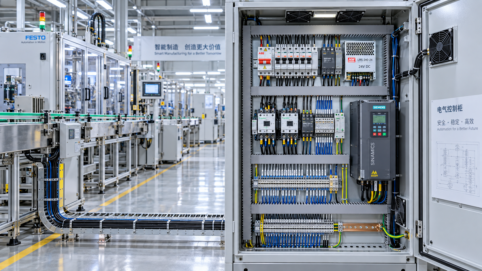
Size the Load, Not Just the Nameplate
A reliable control panel is rarely made reliable by one oversized part. It is made reliable when breakers, contactors, conductors, power supplies, terminals, protective devices, and enclosure ventilation are sized as a coordinated system. The common shortcut—adding up nameplate currents and selecting the next larger component—can produce a panel that passes a basic bench test but trips, overheats, or behaves unpredictably once it sees real production conditions.
For technical evaluators comparing electrical components across suppliers, the starting point is not a catalogue rating. It is a load profile. A control panel feeding a few resistive heaters has a very different sizing problem from one supplying servo drives, solenoid valves, variable frequency drives (VFDs), safety circuits, and a 24 VDC control network. The latter may have modest steady-state current but severe switching peaks, regenerative events, harmonic effects, or a short interruption tolerance.
Before choosing individual parts, document what each outgoing circuit actually does: continuous operation, intermittent duty, motor starting, capacitive charging, heating, braking, or emergency shutdown. This is also the point to establish the applicable regulatory route. Depending on the installation market and machine type, the panel design may need to align with requirements associated with IEC 60204-1, IEC 61439, UL 508A, NFPA 79, or local electrical rules. These standards should not be treated as interchangeable labels; the relevant edition, jurisdiction, assembly method, and end-use conditions need to be checked for the project.
Build a Practical Load Schedule Before Selecting Devices
A useful load schedule includes more than voltage and full-load current. Record the supply system, load type, duty cycle, starting or inrush current, expected simultaneous operation, power factor where relevant, and whether the circuit is safety-related. It should also identify ambient temperature around the panel, installation altitude, cable routing, and the prospective short-circuit current available at the panel incomer.
This last item is often discovered too late. A miniature circuit breaker may have a current rating suitable for a branch circuit but an interrupting rating that is inadequate for the available fault level at the installation point. Conversely, a high interrupting capacity device does not automatically solve coordination issues downstream. Evaluators should ask for the device’s relevant breaking capacity data and then confirm that it suits the calculated or declared fault current of the actual system.
Diversity deserves careful treatment. It is reasonable to account for the fact that not every actuator, heater zone, or auxiliary load will run at the same instant when the operating sequence proves that assumption. It is not reasonable to apply a generous diversity factor merely to reduce panel cost or fit a preferred enclosure. If a PLC program can command several loads simultaneously during startup, cleaning, fault recovery, or manual mode, that state belongs in the calculation.
Protective Devices Must Survive Both Normal Operation and Faults
Protective device sizing has two jobs that sometimes pull in opposite directions. It must avoid nuisance tripping during legitimate transients, while disconnecting a fault quickly enough to protect conductors, equipment, and personnel. Choosing a larger breaker because a smaller one trips is not a diagnosis. The trip may be caused by motor inrush, power supply charging current, a poorly coordinated downstream fuse, a defective load, or an unrealistic grouping of loads on one branch.
For motor feeders, separate the functions in your review: short-circuit protection, overload protection, switching, and isolation. A motor protection circuit breaker, fuse combination, or starter assembly may combine some functions, but the applicable ratings and coordination conditions still need to be examined. Contactor utilization category matters as well. A contactor suitable for a resistive load may not be appropriate for frequent motor starting, reversing, plugging, or demanding inductive switching. Its AC utilization category and manufacturer’s switching data are more useful than a single headline ampere figure.
Do not overlook DC circuits. Interrupting direct current can be more demanding than AC because there is no natural current zero crossing. The polarity, voltage, number of poles used, and the manufacturer’s DC switching or breaking ratings all matter. A device marked with an AC current rating should not be assumed suitable for a 24 VDC branch, especially where inductive loads and repeated switching are involved.
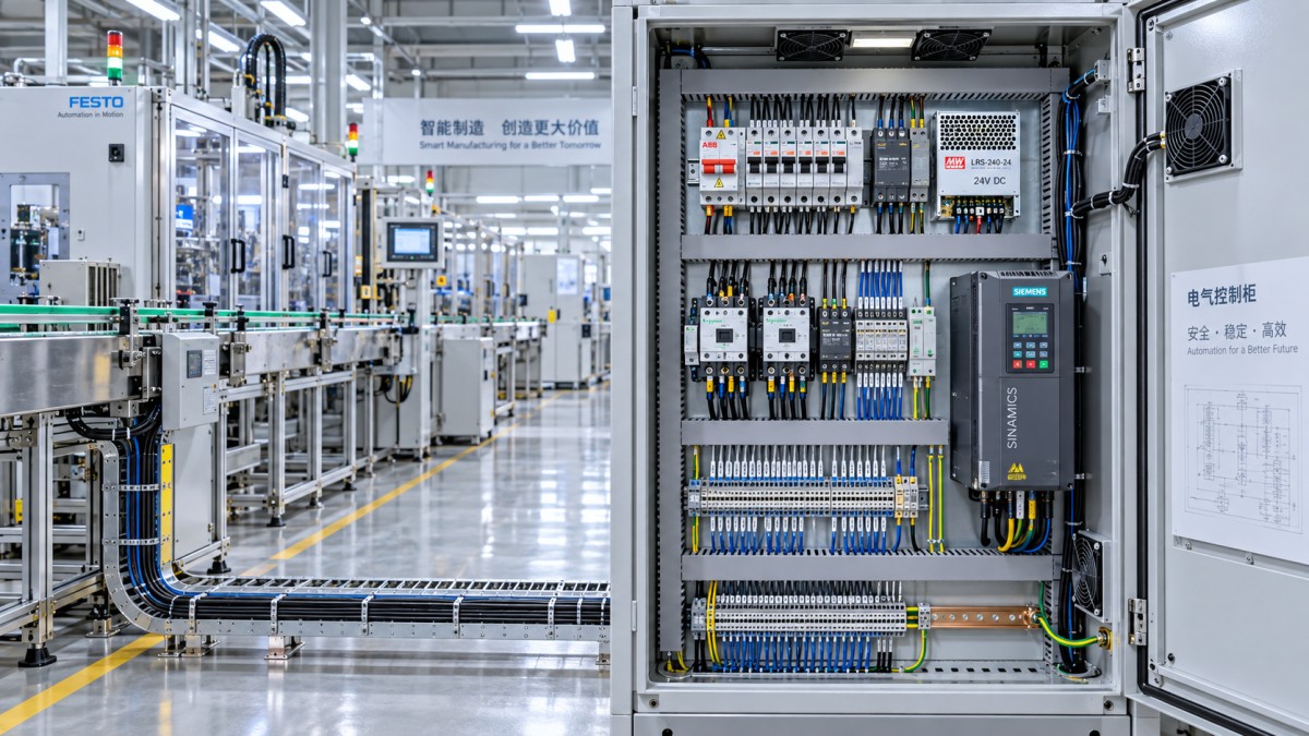
Power Supply Capacity Is More Than the Sum of 24 V Loads
The 24 VDC supply is one of the most frequently underestimated electrical components in a modern panel. PLCs and HMI devices may draw relatively predictable current, but valve banks, contactor coils, electronic sensors, fieldbus devices, and safety modules can create a less forgiving profile. Some loads pull a brief but meaningful current peak at energization; others have a lower holding current after actuation. A supply chosen exactly at the calculated steady-state load leaves little room for these events, supply aging, elevated temperature, or future I/O additions.
Check the power supply datasheet for continuous output rating, overload behavior, peak-current duration, derating curve, and permissible operating temperature. “Boost” functions are useful only when their duration and recovery behavior fit the load event. A supply that can provide extra current for a short pulse may still shut down if several solenoids energize together for longer than expected.
In larger control systems, segmentation is often more valuable than one oversized supply. Separating sensitive controls from valve banks or distributing protected DC outputs can prevent a shorted field device from taking down the controller. The question is not simply whether the supply has enough watts. Ask what fails when one branch faults, whether the critical logic remains alive, and whether the selected electronic circuit protectors or fuses coordinate with the supply’s available fault current.
Conductors, Terminals, and Busbars Need Thermal Discipline
Wire sizing cannot be separated from installation conditions. Ampacity depends on conductor material, insulation temperature rating, ambient temperature, bundling, routing, terminal limits, and the applicable wiring rules. A conductor that is acceptable in open air may operate much hotter in a tightly packed wire duct next to drive output cables and a transformer. That heat can shorten insulation life and raise terminal temperatures even if the circuit breaker never trips.
Terminal blocks should be reviewed with the same seriousness as breakers. Their rated conductor range, tightening method, permissible current, and approved conductor types have to match the actual build. Mixed copper and aluminium conductor arrangements, fine-stranded wires without suitable ferrules where required, or incorrect torque are recurring causes of high-resistance connections. These faults tend to develop quietly: a little heat, discoloration over time, then intermittent voltage drop or a damaged terminal.
For busbars and distribution blocks, consider not only continuous current but short-circuit withstand and physical clearances. Component substitution can be risky here. Two parts may look alike on a distributor page yet have different conditional short-circuit ratings, creepage distances, mounting requirements, or approved upstream protective devices.
Derating Is Where Many “Correct” Designs Fail
Catalogue ratings are generally given under stated reference conditions. In a real enclosure, temperature is rarely uniform. The upper section of a densely populated cabinet can run materially warmer than the lower section, particularly when VFDs, transformers, braking resistors, or power supplies are installed. Devices mounted tightly together may also require spacing or reduced loading according to their documentation.
A credible thermal review considers internal power loss, enclosure material and size, mounting location, external ambient temperature, altitude, and cooling method. Forced ventilation is not a universal answer. Fans introduce dust paths and maintenance needs; filters clog; air-conditioning requires attention to condensation and service access. In dirty industrial environments, reducing heat generation through better component selection or cabinet layout can be more dependable than relying on aggressive airflow.
This is particularly relevant when sourcing across markets. A component offered at an attractive price may be technically legitimate but documented for a different ambient range, supply system, terminal standard, or panel construction practice. Compare the complete datasheet and assembly instructions, not just voltage, current, and dimensions.
Use a Coordination Review Instead of Buying Parts Independently
The strongest panel evaluations work from the incoming supply outward. Confirm the supply characteristics and fault level; select the main disconnect and feeder protection; then assess each branch load, protective device, switching device, conductor, and terminal path. At each stage, verify the ratings that connect adjacent components. This catches mismatches that individual datasheets will not reveal.
Supplier documentation is especially valuable when it includes tested combinations, coordination tables, derating curves, wiring diagrams, and clear statements of the conditions behind a rating. For buyers, importers, contractors, and distributors monitoring component availability, this documentation should be part of the sourcing decision. A replacement part that arrives quickly but lacks compatible technical data can delay approval more than a longer lead-time item with a fully traceable specification.
Before releasing a bill of materials, ask a few blunt questions: Can the device interrupt the available fault current? Will it tolerate the actual inrush? Is its current rating still valid at the expected enclosure temperature? Are the wire, terminal, and protection ratings consistent? What happens when one DC branch fails? And is the selected variant acceptable for the destination market?
Correctly sized electrical components are not necessarily the largest or most expensive options. They are the parts whose ratings remain credible after load behavior, fault conditions, installation environment, coordination, and service realities have all been considered. That discipline is what keeps a control panel stable long after commissioning, when the cabinet door is closed and the process is no longer forgiving.
Technical Specifications
- When DIN rail terminal blocks need end stops to prevent looseningAuthor :Electrical Components Editorial Team
- How to size electrical components for a reliable control panelAuthor :Electrical Components Editorial Team
- What drives the price of LED panel lights for office projects?Author :Electrical Components Editorial Team
Expert Insights

Chief Security Architect
Dr. Thorne specializes in the intersection of structural engineering and digital resilience. He has advised three G7 governments on industrial infrastructure security.