How mold design affects warpage in automotive injection molding
Author
Date Published
Reading Time
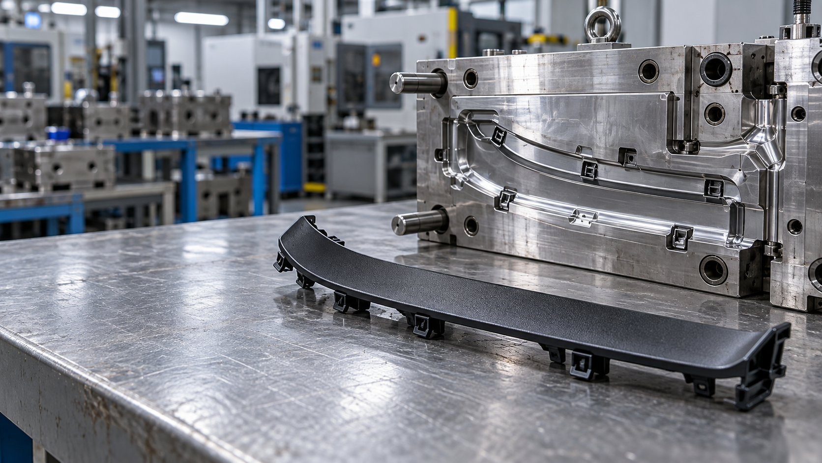
A molded automotive component can look acceptable at the press and still create trouble at assembly. A mounting tab may sit high, a seal surface may twist, or a long trim piece may pull away from its mating part. These defects are often described simply as warpage, but their causes can be spread across the mold design, material behavior, processing conditions, and measurement method.
In injection molding for automotive applications, mold design determines much more than the shape of the cavity. Gate position, cooling layout, local thickness transitions, and ejection strategy influence how a part fills, packs, cools, and releases. For technical evaluators reviewing a tooling proposal, the challenge is to distinguish a design that merely produces a complete part from one that can consistently meet functional dimensional requirements.
Why molded parts warp after leaving the tool
Warpage is the distortion that occurs when different areas of a molded part shrink by different amounts or are constrained from shrinking uniformly. Some deformation becomes visible immediately after ejection; additional changes can develop as the part reaches ambient temperature or, for moisture-sensitive materials, equilibrates with its environment.
Uneven cooling is a common contributor, but it is not the only one. Differences in packing pressure, wall thickness, molecular orientation, and fiber orientation can all create unequal shrinkage. Residual stresses may also be released when the part is ejected or exposed to later thermal conditions.
For an automotive bracket, housing, or interior trim component, the important question is not whether every surface is perfectly flat. It is whether the predicted and measured shape meets the drawing requirements in the condition in which the part will be inspected and used. A small distortion at a locating feature can matter more than a larger deviation on a noncritical surface.
Gate placement sets the direction of more than flow
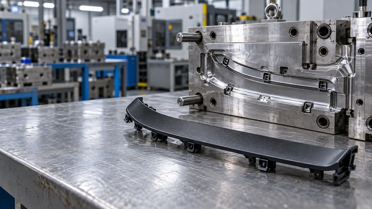
A gate determines where molten material enters the cavity and strongly influences the flow pattern. That pattern affects how pressure is transmitted during packing, where flow fronts meet, and how polymers and reinforcing fibers become oriented. Each of these effects can change the final shape.
Consider a long, narrow component gated at one end. Material must travel a considerable distance to reach the far end, which can make effective packing more difficult there. Depending on the geometry and material, the resulting shrinkage differences may contribute to bowing or twisting. Moving the gate, adding another gate, or changing the runner arrangement may improve pressure distribution, but each choice introduces other considerations.
Multiple gates, for example, can shorten flow paths and reduce pressure demand. They can also create weld lines where flow fronts meet, produce local orientation changes, or leave gate vestiges on visible or functional surfaces. In glass-fiber-reinforced materials, flow-induced fiber alignment can make shrinkage directionally dependent: the part may shrink differently along and across the prevailing flow direction.
A useful tooling review therefore asks for more than a gate location marked on a drawing. It should examine the proposed fill pattern, packing effectiveness at critical features, weld-line positions, gate removal requirements, and the effect of the gate on appearance and assembly surfaces. Gate size and freeze-off timing matter as well: if the gate freezes before the cavity can be adequately packed, raising holding pressure later may have little effect.
Cooling layout: follow the part geometry, not just the tool block
Cooling channels remove heat from the mold, but their influence on warpage comes from how evenly and predictably they control the temperature of the cavity surfaces. A channel layout that is easy to machine may leave a deep core, a thick boss, or the center of a large panel cooling differently from the surrounding material.
When opposite sides of a part cool at different rates, the resulting temperature and shrinkage gradients can cause the part to bend. Local hot spots can also delay solidification and change packing behavior. In complex automotive parts, differences around ribs, clips, and mounting towers may be more consequential than the average mold temperature suggests.
Evaluators should look at channel proximity to critical features, spacing, circuit arrangement, coolant flow, and the ability to control core and cavity temperatures independently where appropriate. Areas with limited access may need inserts or alternative cooling approaches. Conformal cooling can improve access to difficult geometry in some tools, but it should be assessed against manufacturing cost, maintenance, cleaning, and the actual thermal benefit.
Cooling analysis is most useful when it is connected to the complete process. Ask which coolant temperatures and flow conditions were assumed, whether relevant inserts and contact conditions were represented, and how sensitive the result is to reasonable variations. A visually balanced channel drawing alone does not demonstrate balanced cooling.
Wall transitions and ribs: part design becomes a tooling issue
Although wall thickness is primarily a part-design decision, it directly shapes the cavity and cooling strategy. Thick sections generally take longer to cool and may shrink differently from adjacent thin walls. Abrupt transitions can increase that mismatch, while locally thin sections may restrict flow or freeze before areas downstream are adequately packed.
Ribs, bosses, and attachment features are frequent sources of competing requirements. They add stiffness or provide assembly points, but heavy rib bases and thick boss intersections can create localized cooling and shrinkage differences. The evaluator should check whether wall transitions are gradual, whether material can flow and pack into the feature, and whether the proposed tooling can remove heat from the surrounding area.
There is no universal rib thickness that eliminates warpage across all resins and load cases. Material grade, feature height, tooling constraints, and structural requirements all matter. If a design change is proposed, it should be assessed against stiffness, sink, filling, and assembly performance rather than treated as a cosmetic correction.
Ejection can add distortion that looks like a cooling problem
A part that has not developed enough stiffness can deform when it is pushed out of the cavity. Uneven ejector-pin placement, insufficient draft, adhesion to one side of the tool, or high local ejection forces can leave permanent marks or bend a feature. Thin walls and projecting clips are particularly vulnerable.
Review the ejection concept alongside the part’s expected temperature and geometry at release. Support should be distributed so that forces are not concentrated on a fragile edge or visible surface. Draft, surface texture, undercuts, and potential sticking deserve attention because they influence the force needed to remove the part.
Cooling longer may reduce ejection deformation, but it can also increase cycle time and will not necessarily solve a poorly supported release. When a trial part is warped, record whether distortion appears immediately at ejection or develops further during cooling. That observation can help separate release-related problems from broader shrinkage effects.
What a credible warpage simulation should show
Simulation is valuable because tooling changes become more expensive once steel has been cut. It is not, however, a substitute for understanding the assumptions behind the colored displacement plot. The most useful analysis links a predicted deformation to a physical cause and compares it with the way the component will be checked.
- Material definition: Is the proposed production grade represented with appropriate shrinkage, thermal, and, where relevant, fiber-orientation data? A generic material file may not capture the behavior of a specific reinforced grade.
- Process conditions: Are melt temperature, mold temperature, injection profile, holding pressure, packing time, and cooling time realistic for the proposed tool?
- Cooling and tool model: Does the model represent the relevant cooling circuits, inserts, and difficult-to-cool features closely enough to support the decision?
- Comparison method: How is the predicted shape aligned to the nominal geometry? A best-fit comparison can conceal movement at a functional datum, while an unrealistic constraint can exaggerate it.
- Decision value: Does the report compare feasible gate, cooling, or geometry alternatives, and explain their effect on critical dimensions rather than only reporting maximum displacement?
Mesh quality and model type also matter, particularly around thin walls, ribs, and complex junctions. Predictions should be treated as estimates with uncertainty, not as guaranteed inspection results. For a sensitive part, a robust proposal may include a plan to correlate simulation with trial measurements and update the model where the results diverge.
Designing for compensation without hiding the cause
Tool compensation deliberately offsets cavity geometry so that the molded part is closer to nominal after it shrinks and warps. It can be useful when a repeatable deformation remains after practical improvements to gating, cooling, and processing. Yet compensation should not be the first answer to every distorted part.
If a proposed offset is based on an unstable process or an unverified material model, the tool may produce a good result only within a narrow operating window. Compensation can also affect mating features, wall thickness, and the feasibility of future engineering changes. Before accepting it, ask which surfaces will be modified, what trial data or analysis supports the offset, and how the supplier will verify its effect across critical dimensions.
Some corrections can be made by adjusting replaceable inserts; others require more extensive rework. That distinction matters during a technical evaluation because it affects both the cost of iteration and the time needed to resolve an unexpected result.
From tooling proposal to production evidence
A strong review connects design intent to a measurable acceptance plan. Define the datums, fixture method, measurement equipment, and time or conditioning between molding and inspection. A flexible trim component measured freely on a table may give a different result from the same part held at its intended assembly points. Both observations can be useful, but they answer different questions.
For automotive programs, confirm which customer drawings, geometric tolerances, material specifications, and inspection or submission requirements apply to the component. Requirements under systems such as IATF 16949 or customer-specific production-part approval procedures depend on the supplier’s scope and the contract; they do not replace the need to agree on part-specific measurement conditions and acceptance criteria.
During trials, review dimensions across cavities where applicable and across representative production conditions, not just one carefully selected part. Record actual melt and mold conditions, fill and pack settings, cooling time, ejection observations, and any handling before measurement. If results drift, this record makes it easier to distinguish a tooling limitation from process variation or a measurement inconsistency.
The best tooling proposal is not necessarily the one promising zero warpage. It is the one that identifies where distortion matters, explains how the mold design manages the underlying causes, and leaves a clear path for verification and correction. That gives evaluators a firmer basis for comparing suppliers—and a better chance of finding assembly risks while they are still drawings, rather than production interruptions.
Facing technical bottlenecks in manufacturing or looking for more efficient industrial solutions? Leave your details below and let the engineering experts at GIi solve them for you.
“We respect your privacy. Your information is strictly confidential.”
Technical Specifications
- How much energy can LED lighting save in a warehouse?Author :Electrical Components Editorial Team
- How mold design affects warpage in automotive injection moldingAuthor :Polymers & Rubber Editorial Team
- China-Peru Free Trade Agreement Upgrade Enters into ForceAuthor :Industrial Machinery Editorial Team
Expert Insights

Chief Security Architect
Dr. Thorne specializes in the intersection of structural engineering and digital resilience. He has advised three G7 governments on industrial infrastructure security.
Core Sector // 01
Security & Safety
- How mold design affects warpage in automotive injection moldingAuthor :Polymers & Rubber Editorial Team

- When plastics and rubber are the right choice for durable partsAuthor :Polymers & Rubber Editorial Team