How do I prevent connector compatibility problems when upgrading control panels?
Author
Date Published
Reading Time
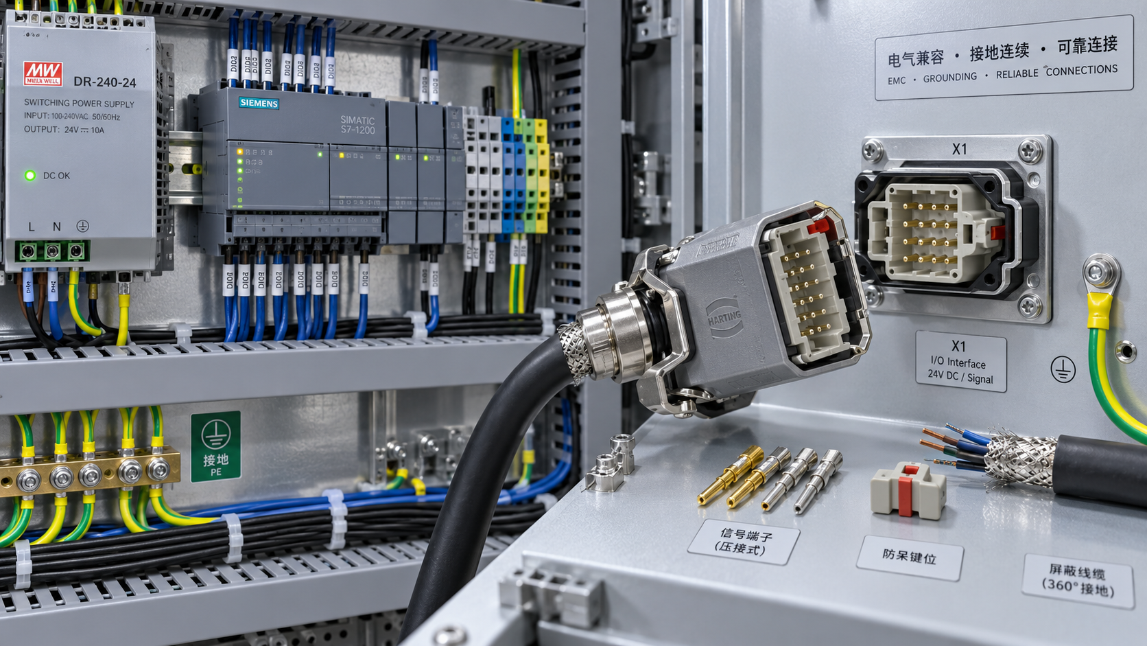
A connector upgrade is compatible only when the entire interface remains valid: electrical ratings, contact assignment, signal behavior, mechanical fit, environmental protection, grounding strategy, and the documentation needed to install and service it safely. A plug that mates physically with an existing receptacle can still create intermittent faults, damaged I/O, overheating, loss of shielding performance, or a panel that no longer complies with its applicable design requirements.
The most effective way to prevent connector compatibility problems is to treat every changed connector as an interface-control change rather than a replacement part. Before procurement, compare the existing and proposed connection at the circuit, cable, panel, and operating-environment levels. Pin count and shell shape are only the starting point.
Start with the function of every contact, not the connector family
Control panels often contain connectors that look similar but serve very different functions: three-phase power feeds, 24 VDC distribution, safety circuits, analogue instrumentation, encoder feedback, Ethernet, fieldbus, servo motor outputs, and cabinet-to-door harnesses. The same multi-pin format may be used across several of these functions, but the electrical and safety consequences of an incorrect connection are not comparable.
Build a connection map from the current panel documentation and verify it against the actual assembly. For each connector, record:
- connector manufacturer, series, part number, and revision where available;
- plug, receptacle, insert, contact, backshell, hood, cable gland, and locking arrangement;
- each pin number and its assigned circuit function;
- nominal voltage, maximum expected voltage, current, and load type;
- whether the circuit carries power, control, safety, analogue, high-speed data, or protective earth;
- wire gauge, insulation type, shielding arrangement, and termination method;
- mating cycles, vibration exposure, temperature, moisture, contaminants, and washdown conditions.
This exercise frequently reveals that the drawing does not fully represent the installed panel. Field modifications, obsolete substitutions, cable repairs, and previous retrofit work can leave a panel with non-standard pin assignments. A proposed upgrade should be evaluated against the installed configuration, not only against the original schematic.
Where connectors are reused between machine sections, identify whether they are intentionally interchangeable. Two identical connectors carrying different circuits create a human-factor risk even if the wiring is technically correct. During a panel upgrade, it may be appropriate to use mechanical keying, coding pins, different shell sizes, distinct colors, or clear connector identification to prevent cross-mating during maintenance.
Separate “can mate” from “is electrically suitable”
Intermateability claims need careful reading. Manufacturers may state that products are compatible within a particular series, but that does not mean every insert, contact type, or accessory is suitable for every circuit. Connector systems can use the same outer shell with different contact sizes, plating options, creepage distances, keying positions, and current limits.
Electrical suitability should be checked at the assembly level. A connector’s headline rating may depend on conductor size, contact arrangement, derating conditions, installation method, altitude, pollution degree, and the number of energized adjacent contacts. It should not be assumed that the highest catalog rating applies to a densely populated control-panel connector.
For power circuits, compare continuous current, inrush current, switching duty, conductor cross-section, terminal temperature rating, and available heat dissipation. Motor starters, solenoids, heaters, braking resistors, and power supplies can impose conditions that differ substantially from their nominal nameplate current. A connector that appears adequate under steady-state current may run too hot when loaded conductors are grouped tightly or when the enclosure has limited ventilation.
For low-voltage control circuits, voltage alone is not enough. Relay outputs, transistor outputs, dry contacts, sourcing and sinking I/O, pulse signals, and reference returns need to be traced individually. A common retrofit failure is assigning a shared 0 V conductor, analogue reference, or functional earth to a different pin because the replacement insert uses a different numbering orientation.
Safety-related circuits require an additional level of discipline. Emergency-stop loops, guard interlocks, safety relay outputs, and dual-channel inputs should not be repinned based on visual similarity. Channel separation, monitoring logic, expected contact behavior, and fault-detection capability must remain intact. Any change that affects a safety function should be assessed within the machine or system’s applicable safety design process, rather than being treated as a routine wiring substitution.
Check pin numbering from the mating face and the wiring side
Pin-numbering errors are among the most avoidable causes of connector incompatibility. Drawings may show the mating face, the solder-cup side, the crimp side, or a cable-end view. Some layouts are mirrored when viewed from the rear. A technician can follow a correct-looking diagram and still place every circuit in the wrong location if the viewing direction is not stated.
The control should be practical and explicit: place the original connector, replacement connector, and drawing side by side; identify the viewing direction; confirm the keyway position; and verify at least one unique reference contact before proceeding with a full harness build. Do not rely on clockwise numbering assumptions. Connector numbering conventions vary by series and contact arrangement.
For critical harnesses, a pin-to-pin continuity test should be performed after termination and before connection to powered equipment. This test should confirm not only continuity from end to end, but also the absence of unintended cross-connections between adjacent circuits, shields, protective earth, and unused pins. Insulation-resistance or dielectric testing may also be appropriate, but test voltage must be suitable for the connected devices; sensitive electronics may need to be isolated before such tests are carried out.
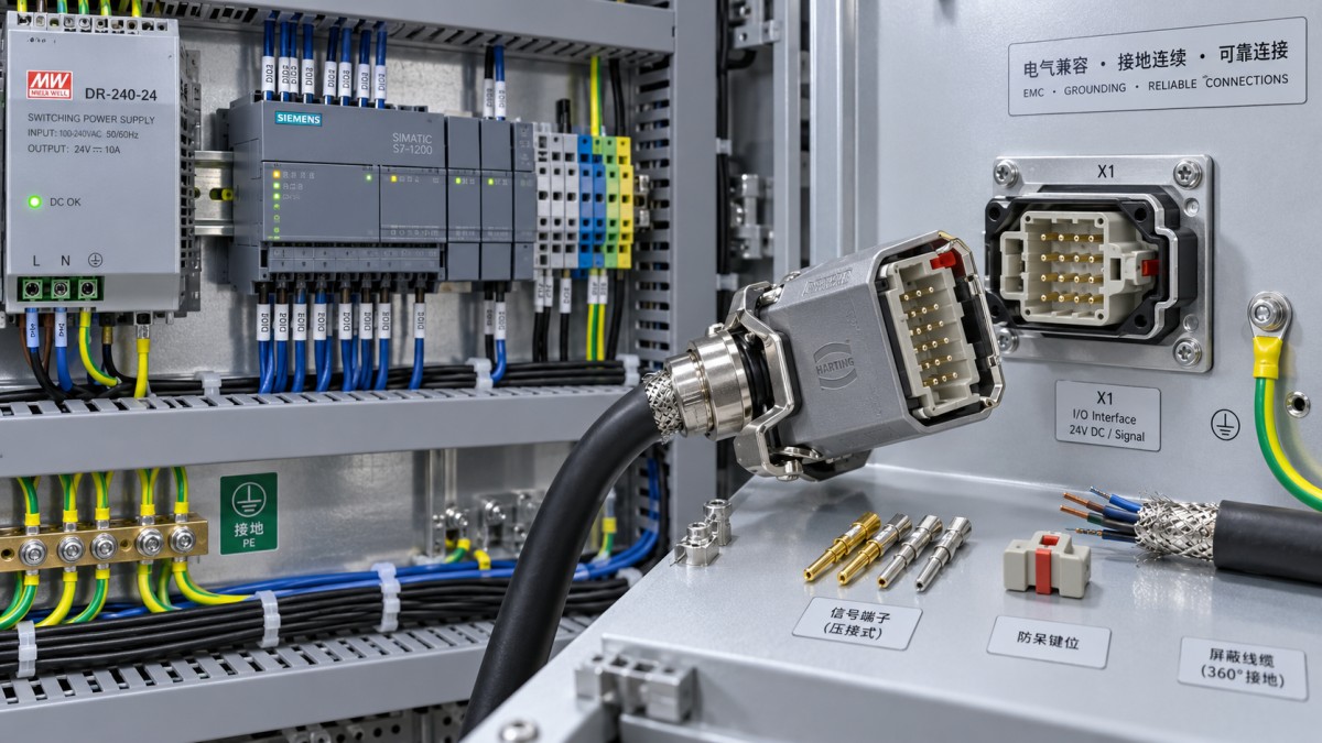
Signal integrity can make a mechanically correct retrofit fail
Connector selection becomes more restrictive when the panel contains analogue signals, encoder feedback, Ethernet, industrial Ethernet, high-speed serial communication, or variable-frequency drive connections. In these circuits, continuity is not equivalent to performance.
Ethernet and other balanced data links depend on controlled pair geometry and impedance. Replacing a connector or field-terminated plug with a general-purpose multi-pin solution can disturb pair twist, shielding continuity, and impedance control. The result may be communication errors that appear only under load, at certain cable lengths, or in electrically noisy conditions. A successful continuity check will not reveal this type of fault.
Encoder and feedback cables deserve similar attention. Differential signals may require individually paired conductors and, in some systems, separate shielding arrangements. Mixing feedback conductors with motor power in a common connector without a design basis can increase susceptibility to electromagnetic interference. If a servo drive upgrade changes the feedback interface—such as moving from incremental encoder signals to a proprietary digital feedback system—the connector may be physically adaptable while the signals are not interoperable at all.
Analogue signals require a defined reference strategy. A 4–20 mA loop, a 0–10 V input, thermocouple circuit, RTD connection, and load-cell signal may all use small-gauge conductors, yet their grounding and shielding requirements differ. Extending or adapting these circuits through an unsuitable connector can introduce noise, ground-loop effects, or measurement drift. Shield terminations should follow the equipment manufacturer’s instructions and the panel’s electromagnetic compatibility design. Connecting every shield to protective earth at both ends is not a universal rule; the correct method depends on the signal type, frequency behavior, cable construction, and system design.
Do not overlook protective earth and bonding continuity
A protective-earth contact is not merely another conductor position. Its mechanical and electrical requirements may differ from those of signal contacts. The connector system should provide an appropriate earth contact arrangement, reliable metal-to-metal bonding where required, and a conductor size suitable for the applicable installation rules.
Problems emerge when a metal connector shell is assumed to provide protective bonding without a verified path, or when a panel door harness is replaced with a connector that interrupts a previously continuous bonding conductor. Paint, anodized finishes, gaskets, corrosion, and mounting hardware can all affect shell-to-enclosure continuity. Functional earth, cable shield bonding, and protective earth should also be distinguished in documentation; combining them casually can create noise problems or compromise protective measures.
Where the panel is designed under IEC 60204-1, UL 508A, NFPA 79, or another applicable framework, connector changes should be reviewed against the requirements governing the actual installation and destination market. These documents do not make one connector universally acceptable or unacceptable. Compliance depends on the assembly, circuit duty, component recognition or certification where relevant, wiring method, spacing, enclosure conditions, and verification process.
Mechanical fit includes enclosure geometry and service access
A replacement connector may have the correct electrical specification but still be unsuitable for the panel. Larger hoods, right-angle cable exits, different locking levers, or a deeper rear termination area can interfere with wire ducts, DIN rail components, door movement, cooling paths, or the enclosure wall.
Measure the complete installed envelope rather than the panel cutout alone. Include bend radius, cable-gland depth, hood clearance, tool access for tightening, connector release clearance, and the force transferred to the panel when a cable is pulled. A connector mounted on a frequently opened door should be assessed for repeated flexing and strain relief. A connector close to a VFD, transformer, or power supply may face higher local temperature and electromagnetic exposure than the ambient enclosure specification suggests.
Ingress protection must be evaluated as an assembled condition. A connector body may be listed with a particular IP rating only when mated, fitted with specified seals, capped when unmated, installed with an approved cable gland, and tightened to the required torque. An unused or temporarily disconnected interface can become the point through which dust or moisture enters the enclosure. For outdoor, food-processing, washdown, marine, or corrosive locations, material compatibility and sealing details deserve the same scrutiny as electrical ratings.
Control obsolescence without creating undocumented substitutions
Upgrades often begin because an original connector is unavailable, has an extended lead time, or no longer meets the preferred component strategy. The risk is not the use of an alternative component itself; the risk is an alternative introduced without a controlled equivalence assessment.
Ask suppliers for the exact data needed to compare the replacement: dimensional drawings, contact arrangement, approved wire ranges, crimp-tool and contact specifications, temperature limits, current and voltage ratings by configuration, sealing accessories, material data, and relevant approval information. A distributor’s description stating “replacement for” should not substitute for manufacturer documentation.
Crimp contacts are particularly vulnerable to informal substitution. Contacts that fit into the same cavity may use different wire ranges, retention features, plating systems, or crimp profiles. A contact can appear fully inserted while having insufficient pull-out strength or elevated resistance. Use the connector manufacturer’s specified contact and tooling combination, or a documented equivalent approved for that system. Reusing old contacts after removal is generally a poor control measure unless the connector manufacturer explicitly permits it and their condition can be verified.
Document the final interface in a way that supports future maintenance: updated schematic, connector table, wire list, pinout drawing, bill of materials, torque or crimp requirements, inspection records, and labels matching the actual panel. A clear revision record prevents the next upgrade from being based on obsolete assumptions.
Verify compatibility before commissioning, not after production starts
A disciplined verification sequence is less disruptive than troubleshooting a finished panel. Begin with document review and physical comparison, then build or modify one representative harness where feasible. Inspect contact seating, keying, cable clamp engagement, shield termination, protective-earth continuity, and label accuracy before connecting active equipment.
Electrical checks should reflect the circuit type. Power connections require polarity, phase, earth, continuity, insulation, and load-related checks appropriate to the equipment. Control I/O requires point-to-point verification against the latest drawings. Network and high-speed communication links should be tested with methods suitable for the relevant medium, rather than with continuity testing alone. Functional testing should confirm expected behavior during startup, normal operation, fault conditions, and connector disconnection where that condition is relevant to the design.
The central question is not whether a new connector can be attached to an old cable. It is whether the upgraded interface preserves the electrical function, protective measures, signal quality, environmental performance, and maintainability of the control panel. When that question is answered with traceable drawings, manufacturer data, and appropriate verification, connector compatibility stops being a late-stage installation risk and becomes a controlled engineering decision.
Technical Specifications
- How to choose construction chemicals for concrete repair substratesAuthor :Chemical Industry Editorial Team
- How do I prevent connector compatibility problems when upgrading control panels?Author :Electrical Components Editorial Team
- How to choose ceramic tiles for bathroom floors with better slip resistanceAuthor :Construction Materials Editorial Team
Expert Insights

Chief Security Architect
Dr. Thorne specializes in the intersection of structural engineering and digital resilience. He has advised three G7 governments on industrial infrastructure security.
Core Sector // 01
Security & Safety
- How do I prevent connector compatibility problems when upgrading control panels?Author :Electrical Components Editorial Team

- What to verify before choosing a control panel supplierAuthor :Electrical Components Editorial Team

- How to size electrical components for a reliable control panelAuthor :Electrical Components Editorial Team

- When does a custom control panel justify its engineering cost?Author :Electrical Components Editorial Team