How to size DC electric motors for continuous-duty applications
Author
Date Published
Reading Time
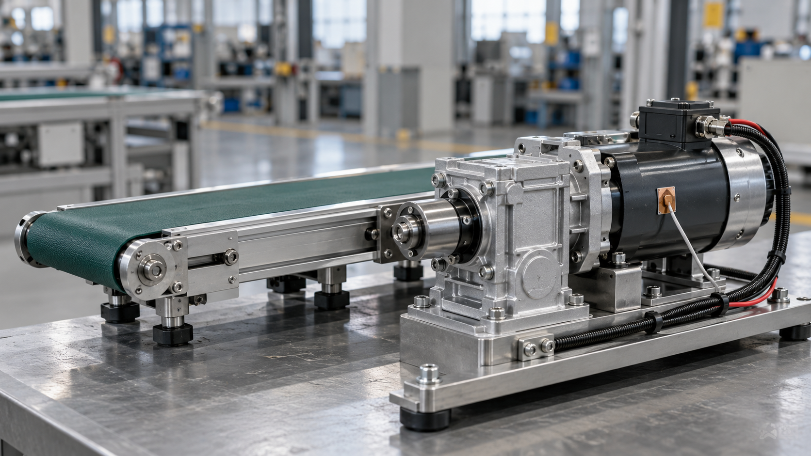
Select DC electric motors for continuous duty by matching the required torque and speed to a manufacturer’s continuous operating envelope under the actual cooling and ambient conditions. Then verify that the motor, controller, and power supply can handle starting, acceleration, and temporary overloads. Nameplate power alone cannot establish suitability: a motor delivering modest mechanical power at low speed can still draw enough current to overheat.
A defensible selection therefore needs two separate results: sufficient torque throughout the operating cycle and acceptable temperature after sustained operation. Gear ratio, enclosure, mounting, supply voltage, and speed control all affect whether those requirements are met.
Define the load at the shaft before choosing a power rating
Begin with the torque and speed required at the driven shaft. For conveyors, mixers, feeders, and similar equipment, distinguish normal running resistance from breakaway friction, material buildup, and occasional process overloads. A single average power measurement can conceal the torque that determines motor size.
Mechanical output power follows:
P = T × n / 9550
Here, P is shaft power in kilowatts, T is torque in newton-metres, and n is speed in revolutions per minute. This relationship converts a defined operating point into power; it does not establish how much torque a motor can sustain thermally.
The load’s behavior across the speed range matters. A conveyor carrying a steady load often requires approximately constant torque, so reducing speed lowers output power without proportionally reducing motor current. A centrifugal fan or pump follows a different torque-speed relationship when operating under similar system conditions. Positive-displacement pumps require separate treatment because pressure, viscosity, and mechanical losses determine torque.
Capture operating conditions that change resistance. Cold lubricant, settled solids, belt tension, and a fully loaded restart can produce requirements absent from an unloaded trial. For a vertical axis, include gravitational torque during motion and holding; a mechanical brake changes the motor’s holding requirement but does not remove lifting torque.
Translate the load through the transmission
When a gearbox separates the motor from the load, calculate the motor-shaft requirement using the reduction ratio and transmission efficiency:
Tmotor = Tload / (i × η)
nmotor = i × nload
In these expressions, i is motor speed divided by load speed, and η is transmission efficiency expressed as a decimal. Use efficiency appropriate to the gearbox type, operating speed, load, and temperature. A catalog’s best efficiency value can understate losses at the intended operating point.
For an illustrative calculation, assume a load requires 30 N·m continuously at 100 rpm, with a 10:1 reduction and an assumed gearbox efficiency of 0.85. The motor must deliver approximately 3.53 N·m at 1,000 rpm, equivalent to about 0.37 kW of mechanical output. These are assumed design inputs, not a product rating. A candidate motor still needs continuous torque capability at that speed and installation condition.
A higher reduction ratio lowers required motor torque and raises motor speed. It also changes acceleration behavior, transmission losses, noise, and maximum output speed. Verify the gearbox’s continuous thermal rating and output torque rating separately; adequate motor capacity does not establish gearbox suitability.
Read continuous torque separately from peak torque
A published peak torque value describes a limited operating condition. Its allowable duration can be constrained by winding temperature, brush commutation, controller current, or permanent-magnet demagnetization limits. Starting torque and stall torque must never be treated as continuous ratings unless the manufacturer explicitly supports continuous operation at that point.
For a permanent-magnet brushed DC motor, electromagnetic torque is approximately proportional to armature current:
Telectromagnetic = Kt × I
Shaft torque is lower because some electromagnetic torque supplies internal losses. Use the manufacturer’s shaft-performance curves when available, and keep torque-constant units and current definitions consistent. Brushless DC motor data requires particular care because phase current, line current, peak current, and RMS current are not interchangeable.
Continuous-duty operation means the motor can remain at the specified operating condition long enough to reach thermal equilibrium without exceeding its limits. Intermittent ratings rely on defined loading and cooling periods. A motor advertised for continuous duty still has boundaries: the designation applies to stated ambient temperature, mounting, cooling, voltage, and speed conditions.
Low-speed operation often sets the thermal limit
Winding copper loss rises approximately with the square of current: Pcopper = I²R. At constant torque, current remains broadly similar as speed falls, while shaft-mounted ventilation weakens. The result is a low-power operating point with substantial heating and reduced heat removal.
This is why selecting a large nameplate power and then reducing speed electronically can produce disappointing results. A motor rated with effective ventilation near its rated speed might require reduced continuous torque at lower speeds. An independently powered blower can preserve airflow, but its benefit must be reflected in the motor’s approved operating data.
Enclosure and mounting also change heat rejection. A sealed motor prevents internal airflow exchange, while a motor designed to conduct heat into a mounting plate depends on that plate’s material, contact area, and temperature. A compact bracket or an insulating interface can invalidate a rating established on a substantial metal heat sink.
Use a supplier’s speed-dependent continuous torque curve or thermal model to evaluate the worst sustained operating point. A single rated-current value is insufficient when cooling changes significantly with speed. Where the application must hold torque at zero speed, obtain an explicit continuous standstill rating.
Ambient temperature means the air surrounding the installed motor, including heat from nearby equipment and recirculated exhaust. Winding insulation class alone does not establish allowable operating temperature: magnets, bearings, brushes, lubricants, and electronics can impose lower limits. Likewise, a cool housing does not prove that winding temperature is acceptable.
Include acceleration without confusing it with continuous loading
Acceleration requires torque in addition to the load’s running resistance. At the motor shaft:
Tacceleration = Jequivalent × α
Equivalent inertia includes the motor rotor, transmission components, and load inertia reflected through the gearing. For an ideal reduction, load inertia reflected to the motor scales with the inverse square of the reduction ratio. Use a consistent transmission model when adding mechanical losses.
A brief acceleration can fit within a motor’s peak capability even when its torque exceeds the continuous rating. Frequent starts change the thermal result. Record the duration and current of acceleration, running, holding, and deceleration rather than treating every cycle as steady running.
For varying load with approximately constant winding resistance, RMS current provides a useful first estimate of copper heating:
IRMS = √[Σ(Ii² × ti) / Σti]
This estimate does not capture speed-dependent cooling, changing resistance, iron losses, brush losses, or local temperature peaks. Long overloads and cycles involving extended low-speed operation require a thermal model or application-specific validation. Average torque alone understates heating when the current profile contains substantial peaks.
Make the electrical operating point achievable
The selected motor must produce the required torque at the required speed using the voltage actually available at its terminals. For a brushed permanent-magnet DC motor, steady operation approximately follows:
V = Ke × ω + I × R + voltage drops
Back EMF increases with speed, while winding resistance and brush, cable, and controller losses consume voltage. As winding temperature rises, resistance increases. A combination that reaches target speed when cold can lose speed under sustained load if voltage reserve is insufficient.
Evaluate minimum supply voltage during operation, including battery discharge where applicable. The controller’s continuous current rating must support sustained motor demand at its installed temperature and cooling condition. Its peak current limit must permit acceleration without exceeding motor or drivetrain limits.
Clarify what current each specification describes. Battery current differs from motor current under PWM control, and a brushless drive’s DC-bus current differs from phase current. Comparing these values directly can lead to an undersized drive or an incorrectly assessed motor.
PWM operation also introduces current ripple and additional losses. Low-inductance motors need a compatible controller and switching strategy. Applications with frequent deceleration or an overhauling load require a defined destination for regenerated energy, such as an accepting power source or a suitably rated braking circuit.
Apply margin to uncertainty, then validate temperature
Choose operating margin from identifiable uncertainties: load variation, friction changes, ambient temperature, supply tolerance, and transmission efficiency. Avoid stacking arbitrary allowances for every component. Excessive motor size adds rotor inertia and can increase the torque available during a jam unless controller limits are set appropriately.
A useful selection record separates calculated continuous torque, required transient torque, and the chosen allowances. Compare candidates at the same motor-shaft speed and cooling condition. When catalog data is incomplete, obtain the continuous torque-speed curve, thermal assumptions, peak-current duration limits, and the meaning of each current rating before accepting the selection.
Final validation should reproduce the installed enclosure, mounting, ventilation, supply, and worst credible load. Run the equipment until temperatures stabilize, or use an established thermal model to justify the required duration. Record motor speed, current, supply voltage, ambient temperature, and available winding-temperature measurements together so that a temperature rise has an identifiable operating context.
If winding temperature is inferred from resistance, account for winding material and measurement conditions; the method estimates average winding temperature rather than the hottest local point. Housing measurements remain useful for comparison and maintenance trending, but require a demonstrated relationship to internal limits.
Acceptance should rest on sustained torque and speed with temperatures below the manufacturer’s limits, plus demonstrated capability for the specified starting and overload events. If the continuous thermal requirement fails, the effective remedy could be a different gear ratio, improved cooling, reduced load, or a different motor design. Increasing nameplate power is only useful when it improves the operating point that caused the failure.
Facing technical bottlenecks in manufacturing or looking for more efficient industrial solutions? Leave your details below and let the engineering experts at GIi solve them for you.
“We respect your privacy. Your information is strictly confidential.”
Technical Specifications
- How to verify the consistency of PVC resin from a supplier in EuropeAuthor :Polymers & Rubber Editorial Team
- How to choose polyethylene grades in Saudi Arabia for film productionAuthor :Polymers & Rubber Editorial Team
- US Finds Imported Robots a Security Threat, Defers Tariffs for 180 DaysAuthor :Industrial Machinery Editorial Team
Expert Insights

Chief Security Architect
Dr. Thorne specializes in the intersection of structural engineering and digital resilience. He has advised three G7 governments on industrial infrastructure security.
Core Sector // 01
Security & Safety
- How to size DC electric motors for continuous-duty applicationsAuthor :Electrical Components Editorial Team

- When should industrial electric motors use variable-speed drives?Author :Electrical Components Editorial Team

- What to verify before choosing a motor drives manufacturerAuthor :Electrical Components Editorial Team

- How motor efficiency ratings affect lifetime energy costsAuthor :Electrical Components Editorial Team

- AC Electric Motors: Which Efficiency Class Fits Your Load Profile?Author :Electrical Components Editorial Team

- Electric Motors: IE Ratings, Efficiency, and Energy CostAuthor :Electrical Components Editorial Team