
How to select valves and fittings for corrosive fluid systems
Author
Date Published
Reading Time
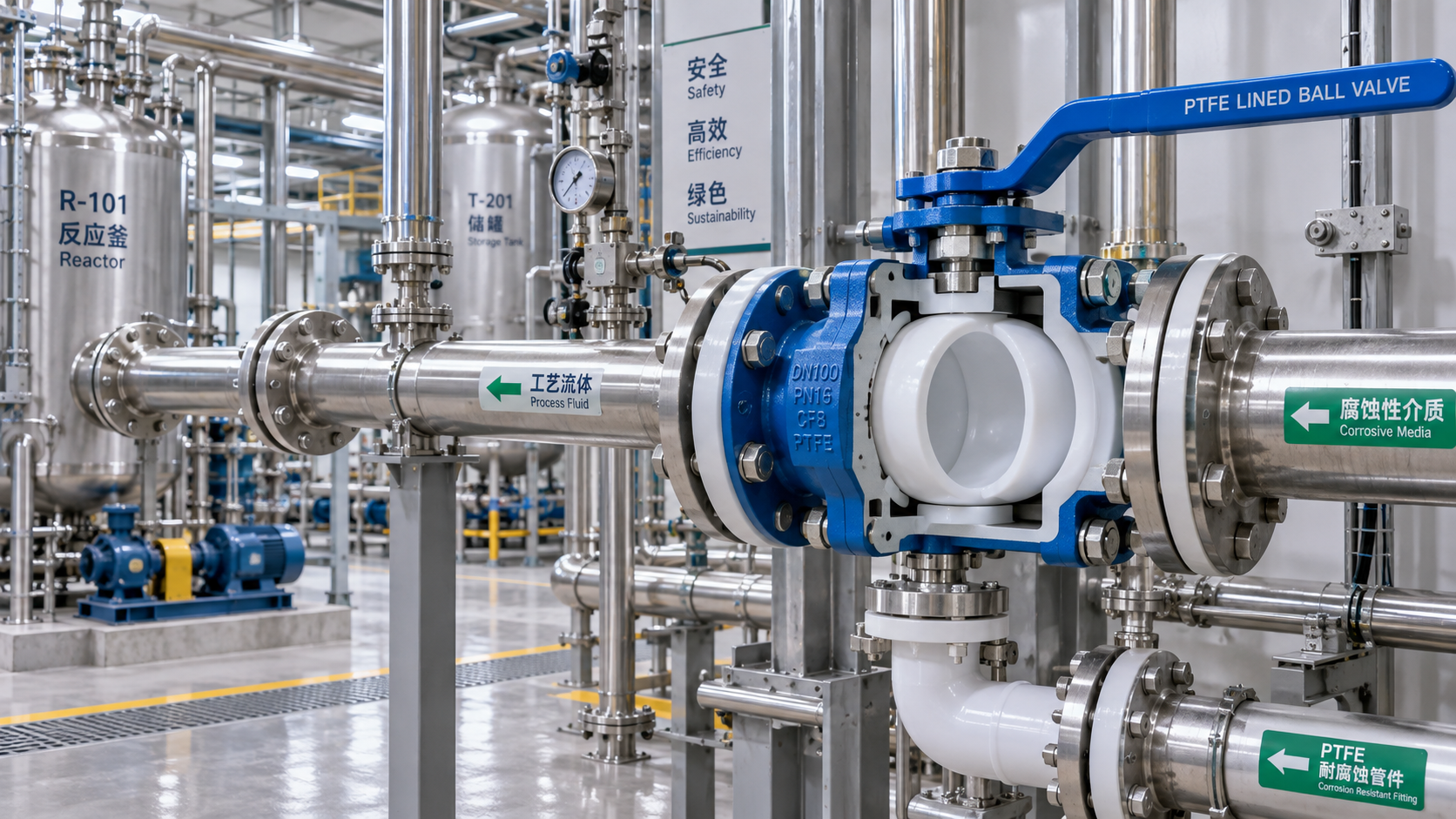
Selecting valves and fittings for corrosive fluid systems starts with the fluid, not the pipe size. A component that performs well in water, air, or mild process chemicals may fail quickly when exposed to acid, caustic solution, solvent, oxidizer, or chloride-bearing media. The usual failure is not always dramatic: it may begin as seal swelling, pitting around a threaded joint, stiff valve operation, or contamination caused by degraded lining material.
The most reliable selection process is to define the complete service condition, then evaluate the valve body, fitting material, wetted internals, and sealing elements as one system. Pressure rating and nominal diameter still matter, but they do not establish chemical suitability on their own.
Start with the actual fluid condition
A chemical name alone is rarely enough to select suitable valves and fittings. Corrosion behavior can change substantially with concentration, temperature, impurities, flow velocity, and whether the system is continuous or intermittent. A material that is acceptable for a dilute chemical at room temperature may be unsuitable for a hotter or more concentrated stream.
Build the service description before requesting quotations or comparing data sheets. It should state:
- The chemical name, including trade names and known contaminants.
- Normal concentration and the highest credible concentration during cleaning, batching, or upset conditions.
- Normal operating temperature and the maximum temperature at the valve or fitting location.
- Operating pressure, pressure spikes, vacuum exposure, and test pressure.
- Whether the fluid is liquid, gas, slurry, vapor, or a two-phase mixture.
- Flow direction, expected velocity, solids content, and whether flow is continuous or intermittent.
- Required valve function: isolation, throttling, diversion, pressure control, non-return protection, or sampling.
This information also exposes conditions that are often missed. A line may carry a compatible chemical during production but see a much more aggressive cleaning fluid during shutdown. A drain point may hold stagnant liquid longer than the main line. A transfer system may experience vacuum during emptying even though its normal duty is pressurized. These conditions can determine the correct design.
Material compatibility is a system decision
For corrosive service, the body material receives the most attention, but the wetted path includes more than the body. Seats, stems, liners, gaskets, packing, diaphragms, bolts, union nuts, and tube inserts may all contact the fluid or its vapor. The system is only as resistant as its least compatible exposed component.
Common material families have different strengths and limitations. Their suitability must always be checked against the defined process condition rather than treated as universal.
Material charts are useful screening tools, but they should not be treated as a complete specification. They commonly indicate broad compatibility and may not cover mixed streams, changing concentration, high velocity, cycling temperature, or contamination from upstream equipment. A chemical compatibility review should apply to every wetted material, including soft parts.
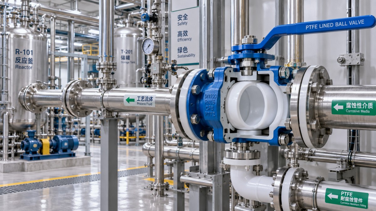
Do not select the valve type before defining its job
A valve used only for full open or full closed isolation can be selected differently from one that must regulate flow. Trying to use an isolation valve for repeated throttling may damage the seat, create unstable control, or accelerate erosion at the restriction point. Conversely, a control valve may add cost and maintenance burden where simple on-off isolation is all that is required.
For corrosive liquids, ball valves are often chosen for compact shutoff and relatively low flow resistance. Their suitability depends heavily on seat material, cavity design, stem sealing, and the risk of trapped fluid. In a volatile or crystallizing chemical service, body cavities can retain liquid after closing. That retained fluid may attack internal parts, solidify, or create pressure as temperature changes.
Butterfly valves can be practical for larger line sizes and applications where a lined wetted path is appropriate. The disc, shaft area, seat design, and end connection must be reviewed carefully. A valve described as lined does not automatically mean every wetted detail has the same resistance.
Diaphragm valves are often considered when containment, external leakage control, or handling of difficult fluids is a priority. Their main selection issue is diaphragm life under pressure, temperature, cycling, and chemical attack. The valve may be chemically compatible while the diaphragm becomes the maintenance-limiting component.
Globe-style control valves and needle valves provide better control in applications that require accurate throttling, but high pressure drop across a small restriction can intensify erosion, flashing, cavitation, or localized corrosion. The trim material and flow path deserve at least as much scrutiny as the pressure class.
Check valves require special attention because their failure can be silent until reverse flow occurs. Select a design based on fluid cleanliness, orientation, pressure drop, closing behavior, and the consequences of backflow. Spring materials, hinge pins, seals, and internal guides may be more vulnerable than the main body.
Fittings are often the first weak point
It is common to specify a corrosion-resistant valve and then connect it with less suitable fittings, adapters, fasteners, or gaskets. This can create a localized failure point immediately beside the component selected for the most severe duty.
Threaded connections deserve particular caution in corrosive systems. Threads create crevices that can retain fluid, complicate cleaning, and concentrate corrosion. Thread sealants must also tolerate the chemical and temperature. If leakage containment, cleanliness, or frequent disassembly is important, a flanged, union, welded, or purpose-designed compression connection may be more appropriate, depending on the piping material and maintenance needs.
For plastic piping, the fitting method is part of the pressure and corrosion design. Solvent-cemented, fusion-welded, flanged, threaded, and mechanical joints each have different limitations. A fitting that is chemically compatible may still be unsuitable if the joint is exposed to pipe movement, thermal expansion, external loads, or repeated dismantling.
Mixed-metal connections require careful review. Dissimilar materials in the presence of a conductive fluid can create galvanic corrosion risk. The actual risk depends on the metal pair, exposed area ratio, electrolyte, and electrical continuity. Simply choosing a more corrosion-resistant valve does not eliminate this issue when it is joined to a less resistant piping material.
Seals, packing, and gaskets decide whether the system stays contained
Many corrosive-service leaks originate from elastomers rather than from the valve body. Seat rings, O-rings, stem packing, diaphragm materials, and flange gaskets should be specified by chemical resistance, temperature, pressure, and mechanical behavior. A seal can be chemically resistant yet still fail because it hardens, swells, cold-flows, wears under cycling, or loses compression after temperature changes.
Consider how the valve will operate. A manually actuated valve that cycles a few times per year places different demands on the packing than an automated valve operating repeatedly each day. Rotating stems, abrasive solids, high-temperature cycling, and vacuum service all affect seal performance.
External environment matters as well. Chemical vapors, washdown exposure, salt-laden air, and splash zones can corrode bolts, actuators, brackets, and stem hardware even when the wetted materials are correct. A contained process line can still fail from the outside in.
Pressure rating must include transient and vacuum conditions
Do not compare only the stated line pressure with the published pressure rating. The relevant condition includes pump start-up, rapid valve closure, blocked discharge, thermal expansion of trapped liquid, pressure testing, and possible vacuum. Corrosive fluid systems often use long runs, elevated tanks, transfer pumps, or batch operations that introduce pressure conditions not visible in the normal operating value.
Vacuum is particularly important for lined valves, plastic valves, and thin-wall piping components. A system can enter vacuum during draining, cooling, pump suction, or improper venting. The body may be strong enough for internal pressure but not designed to resist collapse, liner deformation, or seal displacement under external pressure.
Temperature should be assessed at the component, not only at the process vessel. Heat tracing, solar exposure, nearby equipment, steam cleaning, and exothermic mixing can create local temperatures that exceed the bulk fluid temperature. Thermal expansion can also place significant stress on rigid fittings and valve end connections.
Specify the connection, actuation, and maintenance requirements early
Connection standards and face-to-face dimensions affect more than installation convenience. An incorrect flange arrangement, incompatible pipe schedule, or mismatched end connection can lead to field modifications that compromise corrosion resistance. Specify pipe material, connection type, dimensional standard, gasket arrangement, and fastener materials together.
For automated valves, define the actuator environment and fail position. In corrosive service, an actuator may need protection from chemical vapor, splashes, dust, or outdoor weather. The fail-open, fail-closed, or fail-in-place decision should follow the process hazard and operating consequence. It should not be selected merely because a certain actuator configuration is easier to source.
Maintenance access also changes the preferred design. A valve that requires full line disassembly to replace a seat may be acceptable in a low-use utility line but costly in a process that cannot remain offline. Where regular inspection is necessary, unions, removable spools, drain points, and isolation arrangements should be planned into the piping layout.
A practical verification sequence before purchase
Once a preliminary choice has been made, use a disciplined review rather than relying on a generic “corrosion-resistant” description.
- Confirm the complete fluid profile, including cleaning agents, contaminants, maximum concentration, and upset conditions.
- List every wetted component material: body, lining, trim, seat, stem, packing, gasket, and fitting components.
- Match the valve design to the operating function, cycle frequency, flow behavior, and required shutoff performance.
- Check normal pressure, surge conditions, test conditions, and vacuum exposure against the full assembly rating.
- Review end connections, fasteners, pipe support, thermal movement, and the risk created by dissimilar materials.
- Require clear product documentation that identifies materials and service limitations rather than accepting an unspecified equivalent.
- Confirm inspection, spare-part, cleaning, and replacement requirements before the system is installed.
One of the most expensive mistakes is accepting a valve or fitting based on a nominal material description alone. “Stainless,” “plastic,” or “PTFE-lined” is not a complete selection statement. The grade, construction, seal materials, pressure-temperature limits, and process conditions determine whether the component is appropriate.
When a more expensive option is justified
Higher-cost valves and fittings are justified when failure would create a significant containment, safety, production, environmental, or product-purity problem. The objective is not to specify the most exotic material everywhere. It is to avoid placing a low-margin component at a location where it controls system reliability.
A less costly material may be entirely suitable for a short-lived, low-temperature, low-pressure transfer duty with known chemistry. The same material may be a poor choice in a hot recirculating loop, a concentrated chemical injection point, or a line exposed to frequent cleaning cycles. Selecting by the harshest credible local condition is usually more reliable than selecting by average plant conditions.
Before finalizing the order, make sure the procurement description preserves the technical decision. State the fluid service, body and wetted materials, seal materials, valve type, pressure-temperature conditions, connection details, actuation requirements, and documentation needed for acceptance. That level of clarity reduces the chance that a technically different substitute enters the system under the same product name.
Technical Specifications
- Which doors and windows for residential homes reduce outside noise?Author :Construction Materials Editorial Team
- How to select valves and fittings for corrosive fluid systemsAuthor :Industrial Machinery Editorial Team
- How much capital is needed to start a sanitary ware manufacturing plant?Author :Construction Materials Editorial Team
Expert Insights

Chief Security Architect
Dr. Thorne specializes in the intersection of structural engineering and digital resilience. He has advised three G7 governments on industrial infrastructure security.
Core Sector // 01
Security & Safety