What Causes Power Supply Failures After Installation?
Author
Date Published
Reading Time
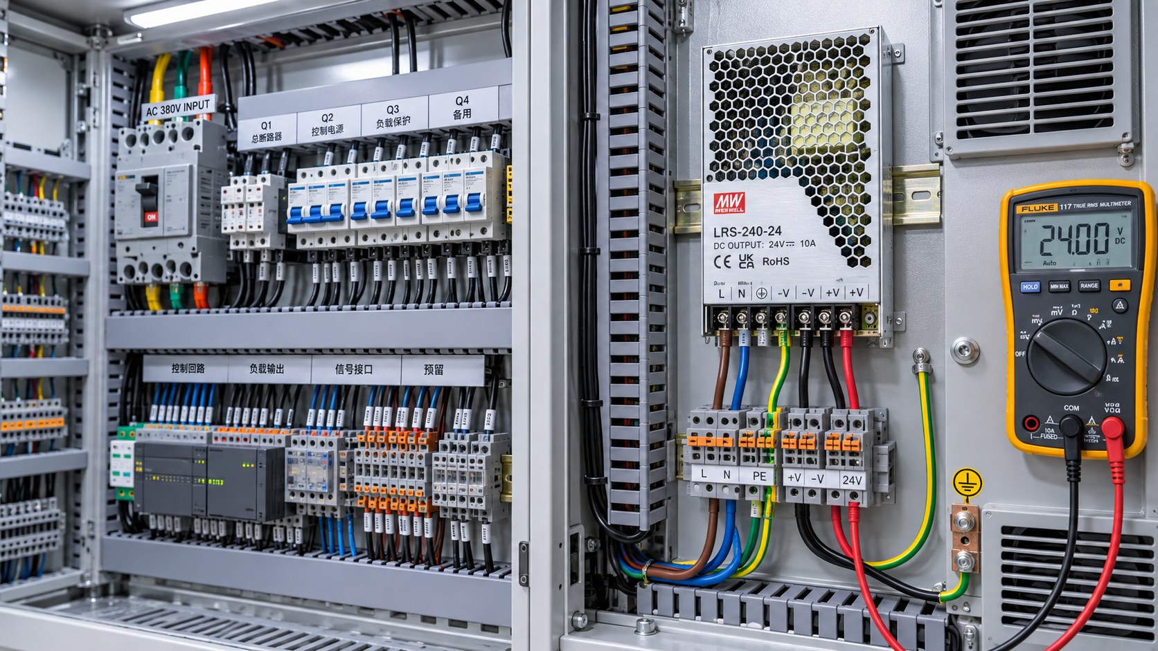
A power supply that fails shortly after installation is not automatically defective. In many cases, the unit is being exposed to conditions outside its electrical, thermal, mechanical, or load limits: incorrect input wiring, a poor earth connection, excessive inrush current, blocked airflow, unstable mains voltage, or an output load that does not behave as expected during startup.
The timing of the failure matters. A unit that does not power on at all suggests an installation, protection, or compatibility issue. A unit that runs briefly and then shuts down often points to overload or overheating. Repeated failures after days or weeks usually require a wider check of the supply environment, including voltage quality, cabinet temperature, grounding, moisture, vibration, and the characteristics of connected equipment.
Incorrect input wiring can damage a supply immediately
Input-side wiring errors are among the most direct causes of post-installation failure. Common problems include connecting a supply configured for one nominal voltage range to a different mains voltage, miswiring line and neutral where the equipment design requires a defined connection, using the wrong terminals, or leaving an input selector in the wrong position on older manually selectable models.
A power supply with a universal AC input range is more tolerant than a fixed-range version, but it still has limits. A 100–240 V AC unit should not be assumed to withstand all industrial power conditions. Sustained overvoltage, a supply frequency outside the specified range, or a transient event can stress the input rectifier, bulk capacitors, surge suppressors, and switching components.
Three-phase installations create additional risk. A single-phase supply connected across phases may receive a much higher voltage than intended, depending on the local distribution system. This is particularly important where installations are assembled across markets with different line-to-line and line-to-neutral arrangements. The nameplate voltage range, wiring diagram, and terminal markings should govern the connection—not assumptions based on plug type, cable color, or the previous equipment installation.
Loose terminals are less dramatic but equally important. A poor connection increases resistance, generates heat, and can produce intermittent input loss or arcing. This may look like an internal power supply fault even when the real issue is at the terminal block, isolator, circuit breaker, or cable lug.
Voltage quality is different from nominal voltage
A site may be described as “230 V” or “480 V,” yet still present conditions that are unsuitable for a particular power supply. Long cable runs, lightly regulated generators, switching of large motors, capacitor banks, welding equipment, and poor distribution design can produce dips, swells, spikes, and interruptions.
Short voltage dips can cause a supply to reset if its hold-up time is insufficient for the application. Repeated dips can also lead to fault logs, controller restarts, dropped communications, or contactor chatter that is wrongly attributed to the DC supply. High-energy surges may destroy protective components or gradually degrade them. A supply may continue working after one event but fail later because protective margin has been reduced.
DC-input power supplies face a related problem: reverse polarity, excessive ripple, voltage overshoot, and poorly controlled charging sources. Battery-backed systems deserve particular attention because nominal battery voltage says little about actual voltage during charging, equalization, load rejection, or low-temperature operation.
Where power quality is uncertain, diagnosis should include measurement rather than a one-time multimeter reading. A handheld meter can confirm basic voltage, but it may not capture short transients, rapid dips, or waveform distortion. The appropriate monitoring method depends on the suspected fault and the consequences of a missed event.
Overload is not always a simple watts calculation
A common selection error is to add the rated wattage of connected devices and choose a supply slightly above the result. That approach can miss the load behavior that actually determines whether the supply survives installation.
Many loads draw substantially more current at startup than during steady operation. Motors, solenoids, valves, lamps, capacitive input circuits, printers, refrigeration controls, and devices with large onboard capacitors can create short but severe demand peaks. A supply may be rated for the steady-state current while lacking sufficient peak-current capability, overload duration, or energy reserve for startup.
Capacitive loads are especially relevant in automation panels and electronic assemblies. When power is applied, discharged capacitors initially appear close to a short circuit. If several devices energize at once, the supply may enter current limit, hiccup protection, or latch-off protection. The resulting repeated startup cycle can be mistaken for a faulty unit.
The opposite condition can also matter. Some regulated supplies require a minimum load for stable operation, particularly older or specialized designs. Modern switch-mode supplies often tolerate no-load operation, but that characteristic should be confirmed from the manufacturer’s documentation rather than assumed.
Output voltage should be measured at the load terminals while the system starts and operates. Measuring only at the supply output can hide voltage drop in undersized cables, corroded connectors, long runs, or shared return conductors. A 24 V DC unit may appear healthy at its terminals while a remote controller receives too little voltage during a current surge.
Parallel and redundant supplies need deliberate design
Installing two power supplies does not automatically provide twice the output current or reliable redundancy. Units intended for parallel operation may need current-sharing connections, matched output settings, external redundancy modules, or specific wiring arrangements. Without these measures, one unit can carry most of the load while the other remains lightly loaded. The overloaded unit may fail first, leaving the impression that redundancy did not work.
Backfeeding is another overlooked issue. If outputs from separate supplies, battery chargers, or energy-storage devices are tied together without isolation, one source may drive current into another. Some power supplies tolerate limited reverse energy; others do not. The product documentation should state whether reverse-voltage protection, output decoupling, or external diodes are required.
Redundancy also does not eliminate upstream failure modes. Two supplies connected to the same unstable feeder, same overloaded circuit, or same overheated enclosure remain exposed to a common cause.
Heat is often the cause even when the room feels cool
Power supplies convert energy with losses, and those losses become heat. Installation instructions usually specify a permissible ambient-temperature range, required clearance, mounting orientation, derating curve, and restrictions on adjacent heat sources. Ignoring any one of these can reduce service life or trigger thermal protection.
The temperature that matters is the air immediately around the unit and the temperature of critical internal components, not the general room temperature. A supply placed above a variable-frequency drive, inside a shallow sealed box, beside a transformer, or behind a clogged filter may operate in a much hotter microenvironment than expected.
Orientation matters because natural convection depends on it. A unit designed for vertical mounting with airflow from bottom to top may run significantly hotter when installed flat or inverted. Tight side-by-side mounting can also restrict cooling, particularly when several supplies exhaust warm air into the same cabinet space.
Thermal problems do not always cause an immediate shutdown. Electrolytic capacitors, insulation systems, solder joints, and semiconductor components all experience greater stress at elevated temperature. A supply that passes a short commissioning test can still age prematurely if it operates above its intended thermal conditions.
Grounding and bonding problems create both safety and reliability risk
Protective earth is not merely a compliance detail. It can be essential to fault protection, electromagnetic compatibility, surge diversion, and stable operation. A missing or high-impedance earth path can leave metal enclosures at unsafe potential during a fault and can prevent surge energy from being directed as intended.
Grounding problems are especially visible in systems containing sensitive controls, communication interfaces, analog signals, or variable-speed drives. A power supply may be electrically functional, yet noise, common-mode voltage, shield termination errors, or ground loops can cause the connected equipment to reset or behave unpredictably.
There is no universal rule that every DC negative terminal should be bonded to earth. Some systems require bonding, while others require an isolated output for functional or safety reasons. The decision depends on equipment design, applicable installation rules, fault-detection requirements, and the overall control architecture. An improvised bond can create unwanted circulating currents; an omitted required bond can compromise protection.
Protection devices may be incorrectly sized or coordinated
A supply can fail because of the protective device chosen for it, even when the supply itself is correctly rated. The input inrush current of switch-mode power supplies can be many times higher than normal operating current for a brief period. A circuit breaker with an unsuitable trip characteristic may nuisance-trip during energization. Repeated energization attempts can then stress both the supply and upstream switching equipment.
Conversely, an oversized protective device may fail to provide the intended conductor protection or allow a fault to persist longer than the system design permits. On the DC output side, poor coordination can mean that a downstream short circuit shuts down the entire supply instead of isolating only the affected branch.
The right approach is to review inrush data, recommended fuse or breaker characteristics, cable capacity, expected fault current, and the behavior of downstream electronic loads. A breaker selected only by the supply’s nameplate input current may not perform as intended.
Environmental exposure can be underestimated during installation
Dust, conductive debris, moisture, condensation, salt-laden air, corrosive gases, oil mist, and insects can all affect power supplies, especially open-frame, ventilated, or low-ingress-protection designs. The enclosure rating of the overall assembly matters as much as the power supply’s own construction.
Condensation is particularly problematic because it can occur even where the equipment is not directly exposed to rain or washdown. Temperature cycling may bring humid air into an enclosure, followed by condensation on cold components. Corrosion and leakage paths can then develop gradually.
Mechanical conditions also matter. Vibration can loosen terminals, fatigue conductors, damage mounting hardware, and stress heavy components. A supply installed in mobile equipment, near stamping machinery, or on a vibrating frame may need mounting methods and product specifications suited to that environment.
Commissioning can introduce damage before normal operation begins
Failures attributed to installation sometimes originate during testing. Common examples include probing adjacent terminals with a meter lead, shorting the output during adjustment, using an incorrect insulation test procedure, applying test voltage to electronics not designed for it, or disconnecting and reconnecting loads while energized.
Insulation-resistance testing deserves care. High-voltage test equipment may damage surge protection components, input filters, connected control electronics, or power supplies if used across circuits that have not been isolated according to the equipment instructions. The required test method should be established before energizing a completed panel, rather than treating every circuit as if it were a simple cable run.
Output adjustment is another area where small changes can have wider consequences. Raising a nominal DC output to compensate for cable drop may push downstream equipment beyond its allowable input voltage when load current falls. Any adjustment should be evaluated across expected minimum and maximum load conditions.
How failure symptoms narrow the diagnosis
A disciplined diagnosis begins with the symptom, then separates supply failure from system failure.
- No output from first energization: check input voltage, terminal wiring, upstream protection, selector position where applicable, polarity, and whether an external inhibit or remote-control terminal is active.
- Output appears briefly, then disappears: investigate startup inrush, short circuits, overload protection behavior, remote sensing connections, and thermal shutdown.
- Output voltage is low only when equipment runs: check load current, cable voltage drop, connector resistance, supply derating, and peak-load demand.
- Repeated random resets: examine input dips, earth continuity, electromagnetic interference, loose connections, vibration, and intermittent downstream faults.
- Supply becomes unusually hot: verify ambient temperature, airflow path, mounting orientation, clearance, contamination, and actual output load.
- Failure after a storm, switching event, or generator operation: assess surge exposure, grounding, upstream protection, and whether the supply’s input range and transient immunity fit the installation.
What should be verified before replacing the unit
Replacing a failed power supply without examining the installation can create a repeat failure. Before fitting a replacement, record the input voltage at the supply terminals, inspect all terminations for heat damage or looseness, confirm earth continuity where required, measure actual output current, and identify startup peaks or simultaneous load energization.
The enclosure temperature should be checked under realistic operating conditions, not only with the door open during commissioning. Review the supply’s derating information against the measured environment, verify clearance and mounting orientation, and inspect for blocked vents or heat sources added after the original design.
It is also important to compare the replacement unit’s behavior—not just its wattage rating—with the application. Input range, inrush current, hold-up time, overload mode, peak-current capacity, output isolation, remote sensing, parallel capability, ingress protection, and approvals can all affect suitability. A higher-rated supply is not necessarily a safer replacement if its protection characteristics or installation requirements differ.
Post-installation power supply failures are usually traceable to a mismatch between the unit and its real operating conditions. The most reliable corrective action is therefore not simply to replace the component, but to identify whether the mismatch lies in wiring, power quality, load behavior, thermal design, grounding, protection coordination, or environmental exposure. Once that distinction is made, replacement decisions become more reliable and repeat failures become far less likely.
Technical Specifications
- When are low modulus silicone sealants needed for moving joints?Author :Chemical Industry Editorial Team
- Which flooring materials hold up best in high-traffic commercial spaces?Author :Construction Materials Editorial Team
- What to verify before selecting a transformer manufacturer in the USAAuthor :Electrical Components Editorial Team
Expert Insights

Chief Security Architect
Dr. Thorne specializes in the intersection of structural engineering and digital resilience. He has advised three G7 governments on industrial infrastructure security.
Core Sector // 01
Security & Safety
- What Causes Power Supply Failures After Installation?Author :Electrical Components Editorial Team

- Do Imported Power Supplies Need Local Safety Certification?Author :Electrical Components Editorial Team

- How to Size Power Supplies for Industrial Control PanelsAuthor :Electrical Components Editorial Team

- DIN Rail Power Supplies vs Enclosed Power Supplies: What Is the Difference?Author :Electrical Components Editorial Team