How to identify control components causing intermittent machine faults
Author
Date Published
Reading Time
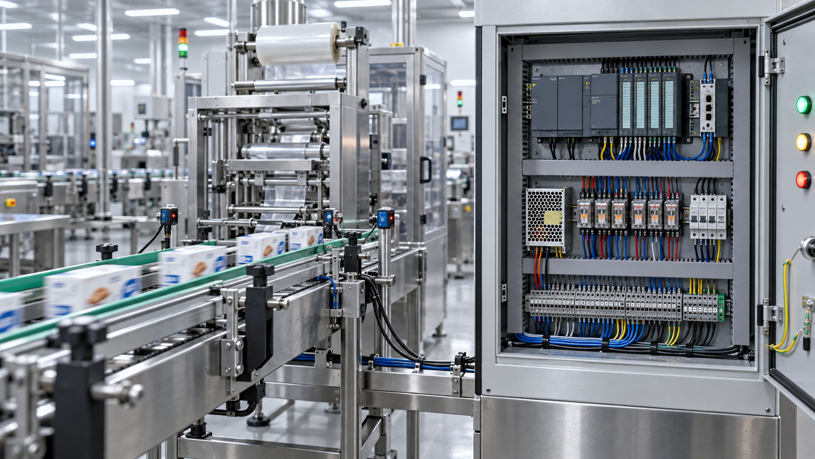
Intermittent machine faults rarely arrive with a clean error code and a failed part sitting in plain sight. A conveyor stops once during a humid morning shift, then runs normally for two days. A packaging line loses its enable signal only after the cabinet has warmed up. A pump starts when a technician is present but trips when the site returns to normal production.
These are the faults that consume maintenance hours because the machine is technically working most of the time. Replacing parts at random may restore operation temporarily, but it can also hide the actual failure mechanism and create unnecessary spare-parts cost. The practical task is not simply to find a defective component. It is to identify which control components become unreliable under the same conditions that trigger the fault.
That distinction matters. A relay may test normally on the bench but drop out when coil voltage falls during a motor start. A proximity sensor may switch correctly at room temperature but miss a target when vibration changes its mounting position. A PLC input may be healthy while the terminal feeding it opens briefly because of a fatigued conductor. Good troubleshooting starts by treating the event as a condition-dependent failure, not a mystery.
Capture the Fault Before Trying to Repair It
The first useful question is not “which part failed?” It is “what changed at the moment the machine failed?” The answer may involve load, temperature, vibration, moisture, supply quality, operator sequence, product position, or another machine starting nearby. A fault that occurs only after an enclosure door is closed points in a different direction from one that occurs when an operator moves a cable carrier.
Record the machine state as closely as possible: active alarms, input and output status, drive state, control voltage, cycle stage, ambient conditions, and what had happened in the preceding few seconds. If the controller has diagnostic history, save it before resetting the system. A reset can erase the most valuable clue: whether the safety chain opened, an input disappeared, an output command was lost, or a downstream device failed to respond.
It is also worth separating the first fault from the secondary alarms. When a control circuit drops out, drives, valves, communication devices, and HMIs may all report consequences. The component that generated the first abnormal signal is usually upstream of the alarm cascade. Chasing the last alarm displayed is a common way to replace perfectly good equipment.
Use the Circuit Logic to Narrow the Search
Intermittent faults become more manageable when the machine is reduced to a signal path. For any failed function, trace the chain from command to action: power source, protective device, safety contact, terminal block, sensor or switch, controller input, logic condition, controller output, interposing relay or drive interface, actuator, and feedback signal.
Do not assume the controller is the center of every problem. In many industrial machines, the PLC only reports what it receives. If an input LED flickers but the logic remains sound, the field device, cable, connector, or input common deserves attention before software changes. Conversely, if the physical signal is stable at the input terminal but the output command disappears under a particular operating sequence, reviewing logic, permissives, communications, and safety conditions becomes more relevant.
A wiring diagram is more than a reference document here. It helps identify shared points. If several unrelated functions fail together, look for common control components: a 24 VDC power supply, shared fuse, common return, safety relay, network switch, field junction, or cabinet ground connection. If only one cylinder or one station misbehaves, the fault is more likely local to that branch.
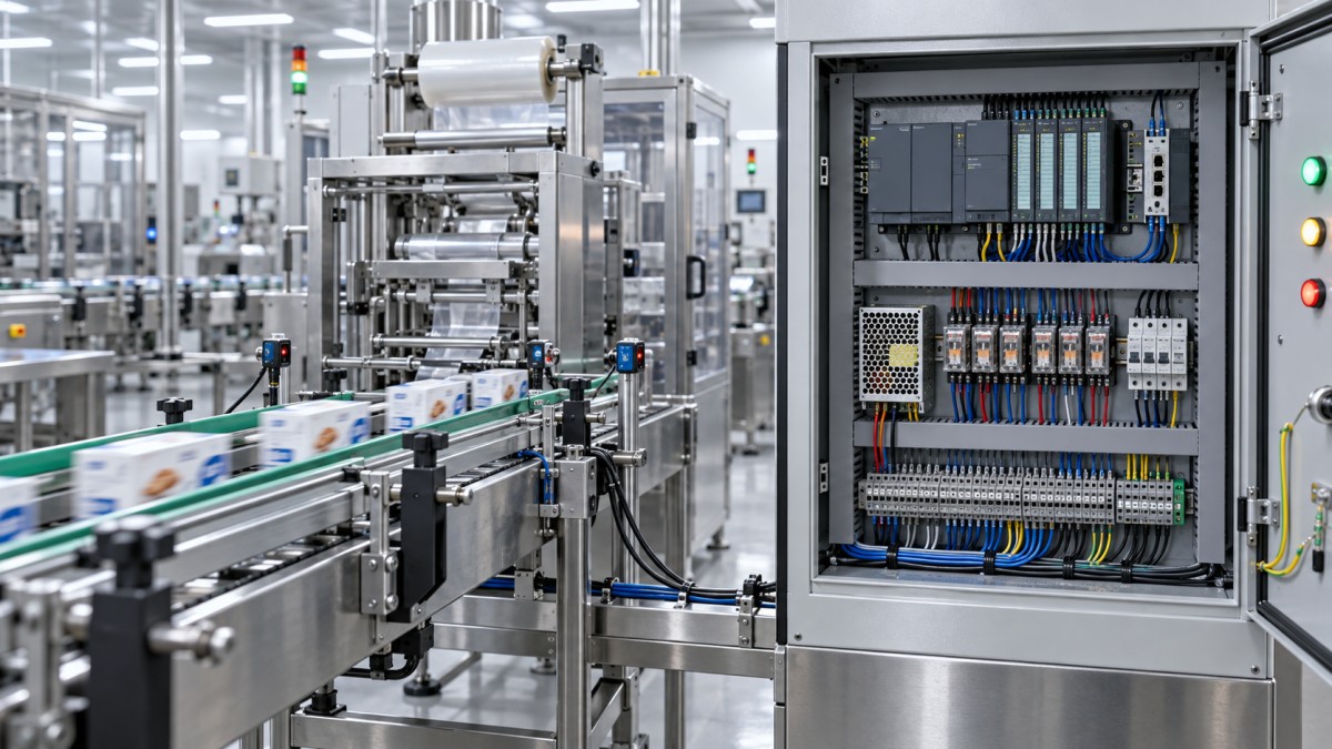
Control Components That Commonly Fail Intermittently
Some parts are repeatedly implicated because their operating environment makes occasional failure more likely. That does not mean they should be replaced first. It means they deserve targeted checks when the symptom fits.
Relays are often blamed because they are visible and easy to replace. Yet a relay that chatters may be reacting to an unstable coil supply rather than causing the instability. Check both sides: what energizes the coil, and whether the contacts carry the expected voltage or signal when energized. Darkened or overheated relay bases, loose socket retention, and contact wear can support the diagnosis, but appearance alone is not proof.
Sensors need the same discipline. A sensor LED showing a switching state does not guarantee a stable signal at the controller. The fault may sit in an M12 connector, a cable crushed near a moving axis, incorrect sensor supply, electrical noise, or a poor 0 V reference. For photoelectric devices, lens contamination and marginal alignment can create brief failures that only occur with certain product colors, surface finishes, or positions.
Measure at the Moment of Failure
A static multimeter reading after the machine has recovered is often misleading. The preferred evidence is a measurement captured during the abnormal event. Depending on the circuit and the site’s safe-work procedures, this may mean using controller diagnostics, a data logger, a meter with recording capability, a scope, or temporary indicator lamps installed at selected test points.
For low-voltage DC systems, compare voltage at the source and at the load while the machine runs through the fault-producing condition. A healthy power supply reading does not rule out voltage loss at a remote valve manifold or sensor cluster. A poor terminal, undersized conductor, damaged cable, or high-resistance return path may only reveal itself when current demand rises.
When electrical noise is suspected, look beyond nominal voltage. Variable-frequency drives, switching loads, poor shielding practice, grounding issues, and routing of signal cables alongside power conductors can affect weak or high-speed signals. It is unwise to declare “electrical interference” without evidence, but it is equally unwise to dismiss it because a handheld meter shows an acceptable average value.
A simple principle helps: test the suspected point under the same thermal, mechanical, and electrical stress that causes the failure. If the machine only faults after forty minutes, a five-minute idle test does not clear the component. If the problem appears during acceleration, test during acceleration. Reproducing the condition safely is usually more valuable than performing many unrelated checks.
Look for Heat, Movement, and Marginal Connections
Three field conditions explain a large share of intermittent control faults: heat, movement, and resistance where there should be a solid connection. Heat can affect relay coils, power supplies, electronic modules, connectors, and terminals. Movement exposes broken strands inside flexible cable, loose pins, poor crimping, and sensor brackets that shift just enough to move outside a reliable detection range.
A visual inspection should be deliberate rather than casual. Check for discoloration around terminals, cracked insulation, moisture ingress, missing strain relief, cable ties pulled excessively tight, unsupported cables near moving equipment, and signs that a connector has been repeatedly bent. With the system safely isolated, gently checking terminal security can reveal issues that are invisible from the front of the cabinet. Follow the equipment manufacturer’s torque requirements where available; overtightening can be as damaging as a loose connection.
Be careful with “wiggle tests.” They can be useful on non-energized wiring or within a controlled diagnostic setup, but random movement of live conductors can create new faults, damage equipment, or expose personnel to risk. The goal is to validate a suspected mechanical weakness, not to provoke an uncontrolled shutdown.
Avoid Parts Swapping as the Main Diagnostic Method
Swapping a suspected module with a known-good spare sometimes has a place, particularly when a production restart is urgent. But it should not become the only evidence. A fault may disappear after a module change because the cabinet was opened, cables were disturbed, the machine cooled down, or the operating sequence changed. The replacement then receives credit it may not deserve.
Before replacing a control component, document why it is suspect. Was its supply correct? Was its command present? Did its output fail? Did the defect follow the component when moved to a suitable test position? Can the fault be linked to heat, vibration, or load? This record prevents the same machine from returning weeks later with a different part replaced but the same hidden fault intact.
Replacement parts also need verification beyond physical fit. Coil voltage, contact configuration, input type, output type, load characteristics, environmental rating, communication version, and safety function can matter. For globally sourced machinery, part availability may vary by region, and a visually similar substitute may not match the original electrical or functional specification. Maintenance teams and purchasing staff should confirm the exact part data from the machine documentation and manufacturer information rather than rely solely on photographs or marketplace listings.
When the Fault Is Not a Single Component
Some intermittent failures are system-level problems. A control cabinet may have insufficient cooling, a grounding arrangement may be inconsistent after a retrofit, or a machine may have acquired additional loads that stress an existing DC power circuit. In those situations, repeatedly replacing sensors or relays treats the symptoms while leaving the operating margin unchanged.
Recent changes deserve special attention: a replacement motor drive, modified tooling, new washdown routine, added field device, cabinet rewiring, different product material, or replacement cable from another supplier. These changes do not automatically cause the fault, but their timing can point the investigation toward a condition that did not exist when the machine was stable.
For equipment owners, contractors, and sourcing teams reviewing recurring maintenance issues across sites, the fault record can also become useful procurement information. Patterns in connector failures, cable durability, relay lead times, or sensor compatibility are relevant when selecting future spares and service partners. Technical news, supply-chain updates, product documentation, and regional availability information can help frame those decisions, but they should support—never replace—measurements taken on the actual machine.
Close the Job With a Repeatable Check
A repair is not confirmed because the machine restarts once. Run it through the condition that previously triggered the problem: normal load, warm cabinet temperature, repeated cycles, motion sequence, or relevant environmental exposure. Review the affected input, output, and alarm history afterward. If a connection was repaired, inspect the routing and strain relief that may have caused it to fail in the first place.
The best maintenance notes are specific: which signal disappeared, where it was measured, under what conditions, what was found, and how the repair was verified. “Intermittent fault fixed” is not enough for the next technician. A short, evidence-based record turns a frustrating one-off shutdown into a faster diagnosis if the pattern returns.
Intermittent machine faults reward patience more than guesswork. Trace the signal path, capture the event, test under real operating conditions, and distinguish a failed control component from the weak connection or unstable supply feeding it. That approach takes more discipline at the start, but it is usually the shortest route to a repair that stays repaired.
- Last One:No more articles
- Next Article:When do acrylic resins provide better UV resistance for outdoor coatings?Sep 25, 2026
Technical Specifications
- How to identify control components causing intermittent machine faultsAuthor :Electrical Components Editorial Team
- When do acrylic resins provide better UV resistance for outdoor coatings?Author :Chemical Industry Editorial Team
- How precision metal fabrication reduces fit-up issues in assembliesAuthor :Metals & Fabrication Editorial Team
Expert Insights

Chief Security Architect
Dr. Thorne specializes in the intersection of structural engineering and digital resilience. He has advised three G7 governments on industrial infrastructure security.
Core Sector // 01
Security & Safety
- How to identify control components causing intermittent machine faultsAuthor :Electrical Components Editorial Team

- What makes a high-reliability sensor suitable for critical equipment?Author :Electrical Components Editorial Team

- When does sensor accuracy become inadequate for process control?Author :Electrical Components Editorial Team

- When does a high accuracy sensor improve process measurement?Author :Electrical Components Editorial Team

- Sensor Selection Guide for Temperature, Pressure, and MotionAuthor :Electrical Components Editorial Team

- 2026 Sensor Trends Shaping Smarter Industrial AutomationAuthor :Electrical Components Editorial Team