How temperature changes affect a MEMS pressure sensor's accuracy
Author
Date Published
Reading Time
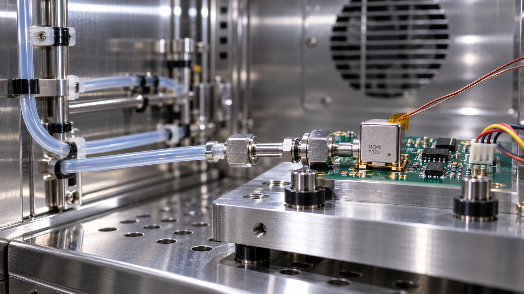
A MEMS pressure sensor can look precise on a room-temperature bench and behave differently inside a hot enclosure or beside a cold process line. The pressure may remain unchanged while the reported value moves. For technical evaluators, that raises an important question: is the sensor detecting a real pressure change, or responding to its own temperature?
Temperature can shift zero offset, alter sensitivity, and introduce mechanical stress through the sensor package and mounting arrangement. Compensation reduces these effects, but its effectiveness depends on calibration, temperature distribution, and operating conditions. Understanding those limits is essential when comparing datasheets and deciding whether a device will meet a system-level accuracy requirement.
How temperature enters the pressure measurement
Most MEMS pressure sensors measure the deflection of a micromachined diaphragm. In a piezoresistive design, resistors on the diaphragm convert mechanical strain into an electrical signal. In a capacitive design, diaphragm movement changes capacitance. Both approaches are temperature-sensitive, although their dominant error mechanisms differ.
For a piezoresistive sensor, temperature changes resistor values and the piezoresistive response. Silicon’s mechanical properties also vary with temperature, affecting diaphragm behavior. Capacitive devices avoid some resistive effects but still experience changes in mechanical response, geometry, parasitic capacitance, and readout electronics.
A useful simplified model is:
Raw output = Z(T) + S(T) × P + R(P,T)
Here, Z(T) is temperature-dependent zero offset, S(T) is temperature-dependent sensitivity, P is applied pressure, and R(P,T) represents residual nonlinear effects. This static model is useful for understanding calibration, but it does not capture every transient or history-dependent error.
Zero offset: the baseline moves
Zero offset is the output at the defined zero-pressure condition. For a differential sensor, that generally means equal pressure at both ports. For an absolute sensor, zero refers to vacuum—not exposure to ordinary atmospheric pressure.
A temperature-induced offset shift can be especially damaging when measuring small pressures. A modest baseline change may represent only a small fraction of full scale yet consume much of the useful signal in ventilation monitoring, filter measurement, or low-pressure flow control.
Sensitivity: the slope changes
Sensitivity describes how much output changes for a given pressure change. If sensitivity varies with temperature, a correction made at zero pressure will not remove the error elsewhere in the range.
This distinction matters during troubleshooting. A sensor that agrees with a reference near zero but increasingly disagrees as pressure rises may have residual span error rather than a simple offset problem. Reliable characterization therefore needs multiple pressure points, not just a zero check.
The package can matter as much as the sensing element
The silicon die does not operate in isolation. Die attach, encapsulants, protective gels, housings, solder joints, and printed circuit boards expand at different rates. Their interaction can transfer stress to the diaphragm or its supporting structure.
As a result, a MEMS pressure sensor may perform differently after soldering, enclosure assembly, or installation with a tightly loaded seal. A compliant adhesive can reduce stress, but its properties may also change with temperature and time. Mounting torque, board bending, and potting can become part of the measurement error.
Thermal hysteresis adds another complication: the output at a particular pressure and temperature may depend on whether the device approached that temperature from above or below. Stress relaxation and material behavior can produce different heating and cooling curves. A calibration based on one direction of travel may not describe both.
Plotting error against temperature for both heating and cooling makes these effects easier to distinguish. A smooth, repeatable curve suggests an error that calibration may address; separated heating and cooling curves indicate a history-dependent component that a single temperature correction cannot fully remove.
Reading a MEMS pressure sensor datasheet without overestimating accuracy
The largest source of confusion is often terminology rather than physics. “Accuracy” may describe room-temperature performance, while a separate specification covers temperature effects. Another supplier may combine several contributors into a total error band. Those figures are not automatically comparable.
Operating temperature is not an accuracy guarantee. A device may function across a broad range while meeting its tightest error specification only over a narrower interval. Storage temperature is a separate rating and does not establish measurement performance.
Also check whether values are typical or guaranteed maximum limits. Typical curves help explain behavior, but they do not establish an acceptance limit for every delivered unit. For procurement decisions, ask whether specifications apply to individual devices, production samples, or qualification testing.
Full-scale error versus reading error
Consider a hypothetical 0–100 kPa sensor with a total error limit of ±0.5% of its 100 kPa span. That corresponds to ±0.5 kPa. At a measured pressure of 5 kPa, the same absolute limit equals ±10% of the reading.
This does not make the sensor unsuitable by definition. It shows why pressure-range selection matters. Oversizing a sensor for occasional pressure excursions may reduce useful low-end accuracy. Compare normal measurement requirements separately from proof-pressure and burst-pressure ratings.
Definitions such as “full scale,” “full-scale span,” and “percent reading” should be checked explicitly, particularly for bidirectional ranges. Do not assume that identical percentage values imply identical absolute errors.
Why compensation works—and where it stops working
Factory compensation usually characterizes sensor output at multiple pressures and temperatures. Stored coefficients allow onboard electronics or an external controller to correct offset, sensitivity, and sometimes higher-order effects.
A digital interface does not itself guarantee good thermal performance. It means the output is digitally encoded; accuracy still depends on the sensing element, calibration coverage, temperature measurement, and correction algorithm. Conversely, an analog sensor can offer strong compensated performance.
Compensation works best when the measured temperature represents the relevant state of the sensing structure. During rapid heating or cooling, that assumption can break down. The temperature sensor, diaphragm, package, and electronics may temporarily sit at different temperatures.
For example, hot process media may heat the diaphragm before the surrounding package stabilizes. A nearby processor can produce the opposite gradient. Even if the final equilibrium reading is accurate, the transition may create a temporary pressure error.
Steady-state thermal accuracy and transient thermal accuracy are different requirements. A compensation table indexed by one temperature value cannot completely describe every spatial gradient, stress state, or thermal history.
A practical thermal evaluation that exposes hidden errors
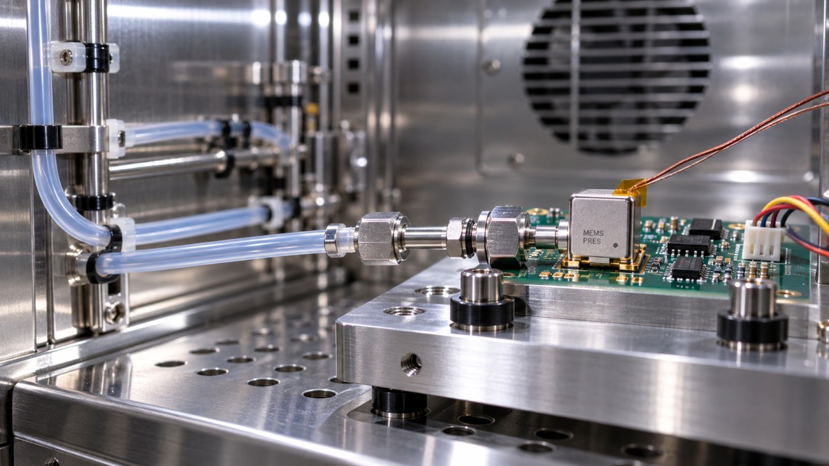
A useful test should reproduce the application’s pressure range, thermal conditions, and installation method. Testing a loose component in a chamber is informative, but it may miss errors introduced by the finished assembly.
- Define acceptance criteria in pressure units. Translate the application requirement into allowable error at relevant operating points. Specify steady-state limits, transient limits, and any permitted settling time.
- Establish a reference-temperature baseline. Measure zero, intermediate pressure points, and the upper measurement limit. Include increasing and decreasing pressure where pressure hysteresis matters.
- Test across the required temperature range. Use multiple temperature plateaus, including endpoints and important operating regions. Verify stabilization using actual assembly behavior rather than chamber air temperature alone.
- Repeat on heating and cooling. This reveals thermal hysteresis and helps separate repeatable temperature dependence from history-dependent behavior.
- Apply representative thermal transitions. Record pressure output and available temperature channels during realistic ramps or process-temperature steps. Evaluate peak error and recovery time.
- Recheck the baseline afterward. A persistent offset change may indicate stress relaxation or lasting change rather than a reversible temperature coefficient.
The reference measurement deserves equal attention. Keep the pressure standard within its specified conditions or account for its temperature dependence. Check tubing, seals, fittings, and pressure sources for leaks or thermal effects.
In a sealed gas volume, temperature can change the actual pressure. Liquid-filled lines can experience thermal expansion effects, and changes in liquid density can alter hydrostatic head. A reading that moves during a chamber test is therefore not automatically a sensor error.
Use multiple devices when assessing production suitability. One sample can reveal a mechanism, but it cannot establish unit-to-unit variation. Record supply voltage, excitation conditions, filtering, sample rate, mounting configuration, and stabilization criteria so results remain reproducible.
Reducing thermal error in the finished system
Start with the thermal environment rather than assuming software will repair everything. Keep the sensor away from concentrated heat sources where practical. Reduce board strain, control mounting loads, and assess adhesives or potting materials in the assembled configuration.
For analog bridges, stable excitation and a suitable ratiometric measurement arrangement can reduce errors associated with excitation variation. They do not eliminate intrinsic temperature effects. Excessive excitation may also cause self-heating, so electrical operating conditions should match those used for characterization.
Application-specific calibration can improve repeatable residual errors. A multi-point pressure-and-temperature calibration is more informative than adjusting one room-temperature offset. However, added calibration cannot reliably remove unpredictable stress shifts, unmeasured gradients, or aging without further characterization.
Filtering may suppress noise and brief disturbances, but it trades response time for smoothness. It should not be used to disguise a thermal excursion that matters to control or safety decisions.
What to require in a technical comparison
Request the complete error definition, compensation range, test conditions, and evidence behind guaranteed limits. If a supplier cites IEC 61298 performance-evaluation methods or another relevant standard, confirm the applicable document, edition, procedures, and reported results. A reference to a test method is not, by itself, proof of a particular accuracy level.
Keep environmental qualification separate from metrological performance. Passing a temperature-cycling or endurance test does not automatically establish pressure accuracy during thermal transitions.
The strongest selection is the MEMS pressure sensor whose documented error bounds match the real pressure range, installation, and thermal duty cycle—not simply the device with the smallest room-temperature accuracy figure. When those conditions are made explicit, temperature becomes a manageable part of the measurement budget rather than an unexplained source of drift.
Facing technical bottlenecks in manufacturing or looking for more efficient industrial solutions? Leave your details below and let the engineering experts at GIi solve them for you.
“We respect your privacy. Your information is strictly confidential.”
Technical Specifications
- How to verify the consistency of PVC resin from a supplier in EuropeAuthor :Polymers & Rubber Editorial Team
- How to choose polyethylene grades in Saudi Arabia for film productionAuthor :Polymers & Rubber Editorial Team
- US Finds Imported Robots a Security Threat, Defers Tariffs for 180 DaysAuthor :Industrial Machinery Editorial Team
Expert Insights

Chief Security Architect
Dr. Thorne specializes in the intersection of structural engineering and digital resilience. He has advised three G7 governments on industrial infrastructure security.
Core Sector // 01
Security & Safety
- How temperature changes affect a MEMS pressure sensor's accuracyAuthor :Electrical Components Editorial Team

- How to identify control components causing intermittent machine faultsAuthor :Electrical Components Editorial Team

- What makes a high-reliability sensor suitable for critical equipment?Author :Electrical Components Editorial Team

- When does sensor accuracy become inadequate for process control?Author :Electrical Components Editorial Team

- When does a high accuracy sensor improve process measurement?Author :Electrical Components Editorial Team

- Sensor Selection Guide for Temperature, Pressure, and MotionAuthor :Electrical Components Editorial Team

- 2026 Sensor Trends Shaping Smarter Industrial AutomationAuthor :Electrical Components Editorial Team