How to size a three-phase transformer for a motor load
Author
Date Published
Reading Time
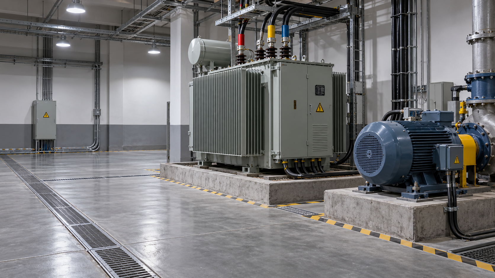
Sizing a three phase transformer for a motor load requires more than matching the transformer’s kVA rating to the motor’s running demand. A motor can draw several times its normal current during startup, causing a temporary voltage dip that affects both the motor and other equipment. Load characteristics, starting method, transformer impedance, and operating conditions all influence the final choice.
For a technical evaluator, the practical question is not simply “What size transformer will run this motor?” It is “What size will run it continuously and start it reliably under the actual system conditions?” The calculation below separates those two tests, then brings them together in a selection process.
Begin with the motor’s electrical input, not its shaft output
Motor horsepower or kilowatts usually describes mechanical output at the shaft. The transformer supplies electrical input, which is higher because the motor has losses and operates at a particular power factor. Whenever possible, use the motor nameplate full-load current and rated voltage rather than estimating from horsepower alone.
For a three-phase load, apparent power is:
Running kVA = √3 × line-to-line voltage × full-load current ÷ 1,000
For example, a motor rated at 460 V and 65 A has an approximate full-load input of:
√3 × 460 × 65 ÷ 1,000 = 51.8 kVA
That figure is the motor’s apparent power at the stated operating point. It is not automatically the transformer rating to order. Other loads, continuous-duty requirements, ambient conditions, and starting performance still need to be assessed.
If nameplate current is unavailable, estimate input apparent power from motor output:
Running kVA = motor output kW ÷ (efficiency × power factor)
Use efficiency and power factor as decimals. This estimate is useful for screening options, but actual manufacturer data should replace assumptions before a purchase decision. Small changes in the assumptions can alter the result, particularly when several motors share one transformer.
Why starting often determines the transformer size
A motor started directly across the line can draw a locked-rotor current several times its full-load current. The exact value depends on motor design and should come from the manufacturer’s starting data or nameplate information. During acceleration, current and torque change as speed rises; a heavily loaded or high-inertia machine may remain in the high-current region longer than a lightly loaded fan.
The transformer does not necessarily need a continuous kVA rating equal to the motor’s starting kVA. The starting event is temporary. However, its impedance and the impedance of the upstream supply and cables create a voltage drop when starting current flows. If the motor terminal voltage falls too far, starting torque falls, acceleration takes longer, and current persists longer. That combination can turn a routine start into a stalled motor or repeated protective trips.
Calculate the initial starting demand
If the locked-rotor current is known, calculate starting apparent power using the same three-phase equation:
Starting kVA = √3 × rated voltage × locked-rotor current ÷ 1,000
For preliminary work, locked-rotor current may be expressed as a multiple of full-load current. For example, if the 65 A motor above has a specified starting current of six times full-load current, its estimated starting demand at rated voltage is:
Starting kVA = 51.8 × 6 = 310.8 kVA
This is a useful indication of the initial demand, not a precise prediction of current at the depressed motor terminal voltage. The actual current depends on the system and motor characteristics. Confirm the manufacturer’s starting data, including the voltage at which it applies.
Check voltage dip rather than relying on a single multiplier
Transformer percentage impedance is central to the starting check. For an initial screening estimate, assuming a stiff primary supply and neglecting cable impedance, the transformer contribution to voltage drop can be approximated as:
Approximate voltage drop (%) ≈ transformer impedance (%) × starting kVA ÷ transformer rated kVA
This simplified relationship treats starting current as fixed at its rated-voltage value and does not fully account for the motor’s changing current, power factor, or system impedance. It is most useful for comparing candidate transformers, not for approving a marginal design.
Suppose the example motor is supplied by a 150 kVA transformer with 4% impedance:
Approximate transformer voltage drop = 4% × 310.8 ÷ 150 = 8.3%
That estimate excludes upstream voltage drop, conductors, and other connected loads. It also does not establish whether the installation is acceptable. Compare the expected motor terminal voltage with the motor and driven-equipment manufacturers’ requirements, and check whether contactors, controls, and other sensitive loads can tolerate the dip. There is no universal allowable percentage that fits every application.
For a more reliable result, request a motor-starting study using the utility source impedance, transformer impedance and X/R ratio, cable characteristics, motor starting parameters, and load torque curve. This is especially important when the supply is weak, the motor is large relative to the transformer, or the acceleration time is long.
Work through a practical selection
Consider the same 460 V, 65 A motor with a 310.8 kVA estimated direct-on-line starting demand. Assume it is the only substantial load for this illustration, and that its starting characteristics and transformer impedances have been confirmed with the equipment suppliers.
The smaller transformer appears adequate for the motor’s running kVA, but its estimated transformer-only starting drop is much larger. The 150 kVA option reduces that contribution, although it could still be unsuitable once source and cable voltage drops are included. Conversely, it may be larger than necessary if the motor uses a different starting method or the driven load has favorable acceleration characteristics.
This comparison illustrates the decision: continuous capacity and starting performance are separate checks. Select a standard transformer rating only after both have been evaluated, along with any applicable loading and installation requirements.
Starting method can change the answer
The starter is part of the sizing problem. It changes the current seen by the supply and may also change the torque available to accelerate the load.
- Direct-on-line starting: Applies full supply voltage to the motor. It is straightforward, but typically places the greatest immediate current demand on the system.
- Star-delta or autotransformer starting: Reduces initial line current, with a corresponding effect on starting torque. Suitability depends on motor connections, load torque, transition behavior, and manufacturer guidance.
- Soft starter: Controls voltage during acceleration and can limit current, but the motor still needs enough torque to accelerate the driven equipment. Bypass arrangements and starting settings matter.
- Variable frequency drive (VFD): Can start a motor with controlled frequency and current, often reducing the abrupt starting demand on the transformer. Evaluate drive input current, harmonics, power factor, and the drive manufacturer’s transformer recommendations rather than applying direct-on-line starting assumptions.
A reduced-current starter is not automatically a cure for an undersized system. If current limiting leaves insufficient torque, the motor may accelerate slowly or fail to start. Compare the motor torque curve with the driven load’s torque requirement throughout acceleration.
Account for the rest of the installation
Motor starting may attract the most attention, but the transformer must also serve its full connected load without exceeding its applicable rating. Include other motors, controls, lighting, heating, and process equipment. For multiple motors, identify the largest credible starting event while other loads are running. If motors can start together after a power interruption, assess that scenario too; a staggered restart sequence may materially change the demand.
Consider these conditions before finalizing the three phase transformer:
- Ambient temperature and cooling: Confirm the transformer’s nameplate rating and whether site temperature, ventilation, enclosure, or altitude requires derating under the applicable standard and manufacturer guidance.
- Loading pattern: Review continuous load, duty cycles, expected peaks, and any permissible short-time loading. Do not assume overload capability without a documented thermal assessment.
- Power quality: Drives and other nonlinear loads can introduce harmonics and additional heating. Specify the expected load profile and ask the transformer supplier whether a harmonic-rated or otherwise suitable design is needed.
- Voltage configuration: Verify primary and secondary voltages, frequency, phase configuration, grounding arrangement, and any neutral requirement. The available motor terminal voltage must remain suitable under running and starting conditions.
- Protection and coordination: Check transformer protection, motor overload protection, short-circuit ratings, and coordination. Transformer energization inrush and motor starting current are different events; both can affect protective-device selection.
- Future loads: Add capacity for a credible expansion plan, not an arbitrary margin that masks an incomplete load schedule. Future motors may also change the starting sequence and voltage-dip assessment.
A larger transformer is not always the only or best remedy for excessive voltage drop. Lower-impedance equipment, shorter or larger conductors, a stronger source, a different starting method, or revised sequencing may solve the problem. Each option has implications for fault current, protection, cost, and operation, so changes should be assessed as a system.
What to send suppliers for a defensible quotation
A kVA figure alone leaves too much room for assumptions. Provide the motor nameplate, full-load and locked-rotor current or manufacturer starting data, starting method, load type, acceleration requirements, and expected start frequency. Include a load schedule, one-line diagram, source fault level or impedance if available, cable lengths and sizes, site conditions, and the voltage-dip limits required by the equipment.
Ask suppliers to state the proposed transformer rating, impedance tolerance or specified impedance, temperature rise, applicable design standard, and any derating assumptions. Where starting is critical, request a documented assessment that identifies what is included in the voltage-drop calculation. An engineer responsible for the installation should verify the final design against local electrical codes and equipment requirements.
The right selection is the smallest suitable solution only after suitability has been demonstrated: adequate running capacity, acceptable starting behavior, compatible protection, and enough information to operate the system with confidence.
Facing technical bottlenecks in manufacturing or looking for more efficient industrial solutions? Leave your details below and let the engineering experts at GIi solve them for you.
“We respect your privacy. Your information is strictly confidential.”
Technical Specifications
- How to verify the consistency of PVC resin from a supplier in EuropeAuthor :Polymers & Rubber Editorial Team
- How to choose polyethylene grades in Saudi Arabia for film productionAuthor :Polymers & Rubber Editorial Team
- US Finds Imported Robots a Security Threat, Defers Tariffs for 180 DaysAuthor :Industrial Machinery Editorial Team
Expert Insights

Chief Security Architect
Dr. Thorne specializes in the intersection of structural engineering and digital resilience. He has advised three G7 governments on industrial infrastructure security.
Core Sector // 01
Security & Safety
- How to size a three-phase transformer for a motor loadAuthor :Electrical Components Editorial Team

- When does a cast resin transformer need high-altitude derating?Author :Electrical Components Editorial Team

- How ambient temperature affects solar transformer specificationsAuthor :Electrical Components Editorial Team

- What to verify before selecting a transformer manufacturer in the USAAuthor :Electrical Components Editorial Team

- How to check transformer capacity for a solar system before commissioningAuthor :Electrical Components Editorial Team

- How to size solar transformer capacity for peak generationAuthor :Electrical Components Editorial Team

- Which solar transformer specifications must match inverter output?Author :Electrical Components Editorial Team

- How do you size a transformer for solar power projects?Author :Electrical Components Editorial Team