How to check transformer capacity for a solar system before commissioning
Author
Date Published
Reading Time
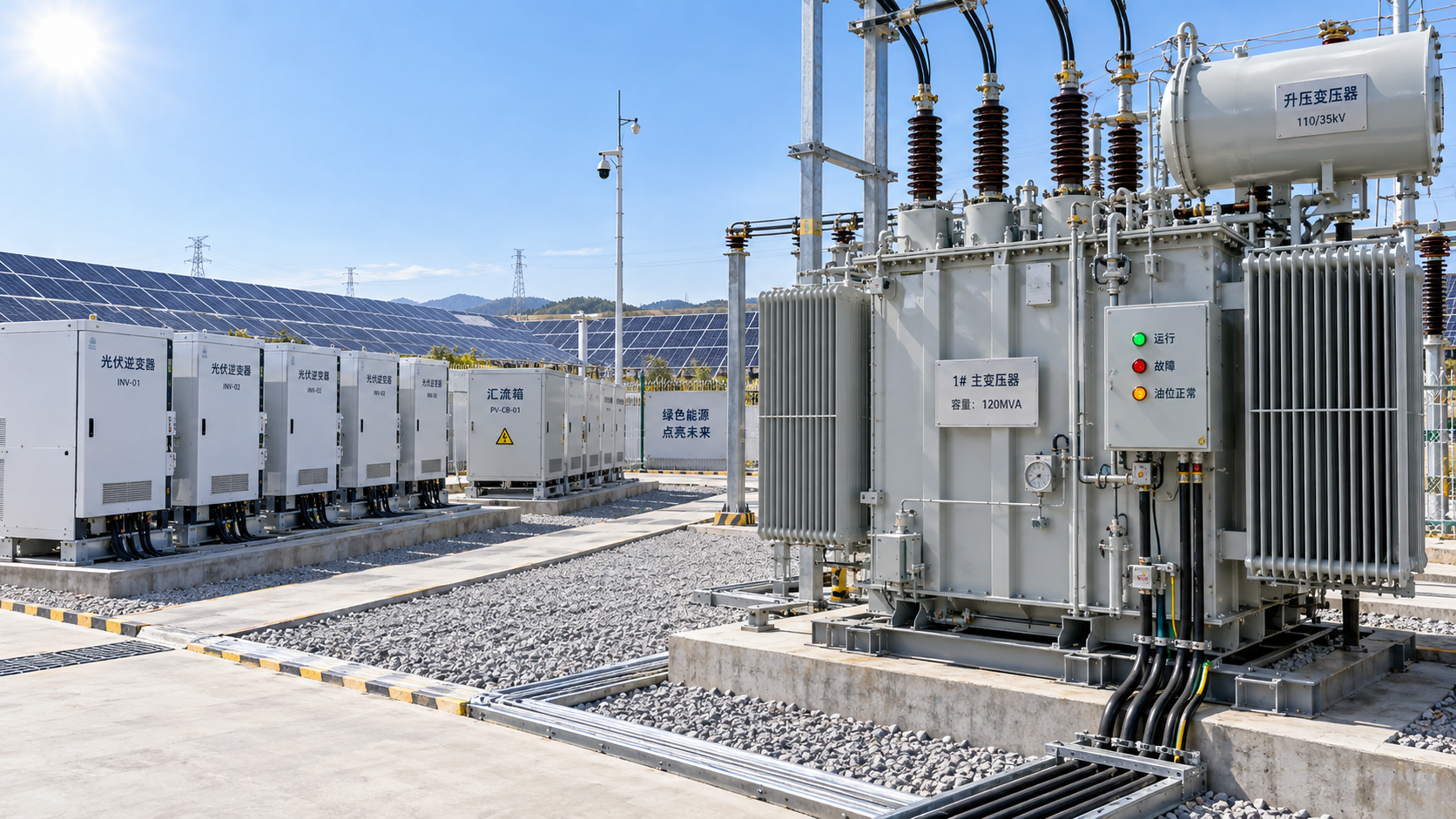
A transformer is suitable for a solar system only when its nameplate rating, thermal condition, voltage ratio, impedance, tap position, protection settings, and connection agreement all support the actual operating envelope. Start with the highest credible AC export condition, then verify that the transformer remains within its continuous and short-duration limits after allowing for site temperature, existing load, reactive power, harmonics, and future solar capacity.
The most common commissioning error is comparing inverter nameplate output directly with transformer kVA and stopping there. Inverter MW, transformer MVA, power factor, local auxiliary demand, and export control must be expressed on a consistent basis before that comparison means anything. A transformer that appears oversized in MW terms can still be constrained by voltage rise, tap range, feeder loading, or an existing load profile that was not included in the study.
Build the correct maximum-load case
Collect the approved single-line diagram, transformer nameplate photograph, inverter data sheets, protection coordination study, utility interconnection conditions, cable schedules, and recent load information for any existing facility supplied through the same transformer. Use approved and as-built documents separately. A design drawing may show a transformer rating or tap arrangement that differs from equipment delivered to site.
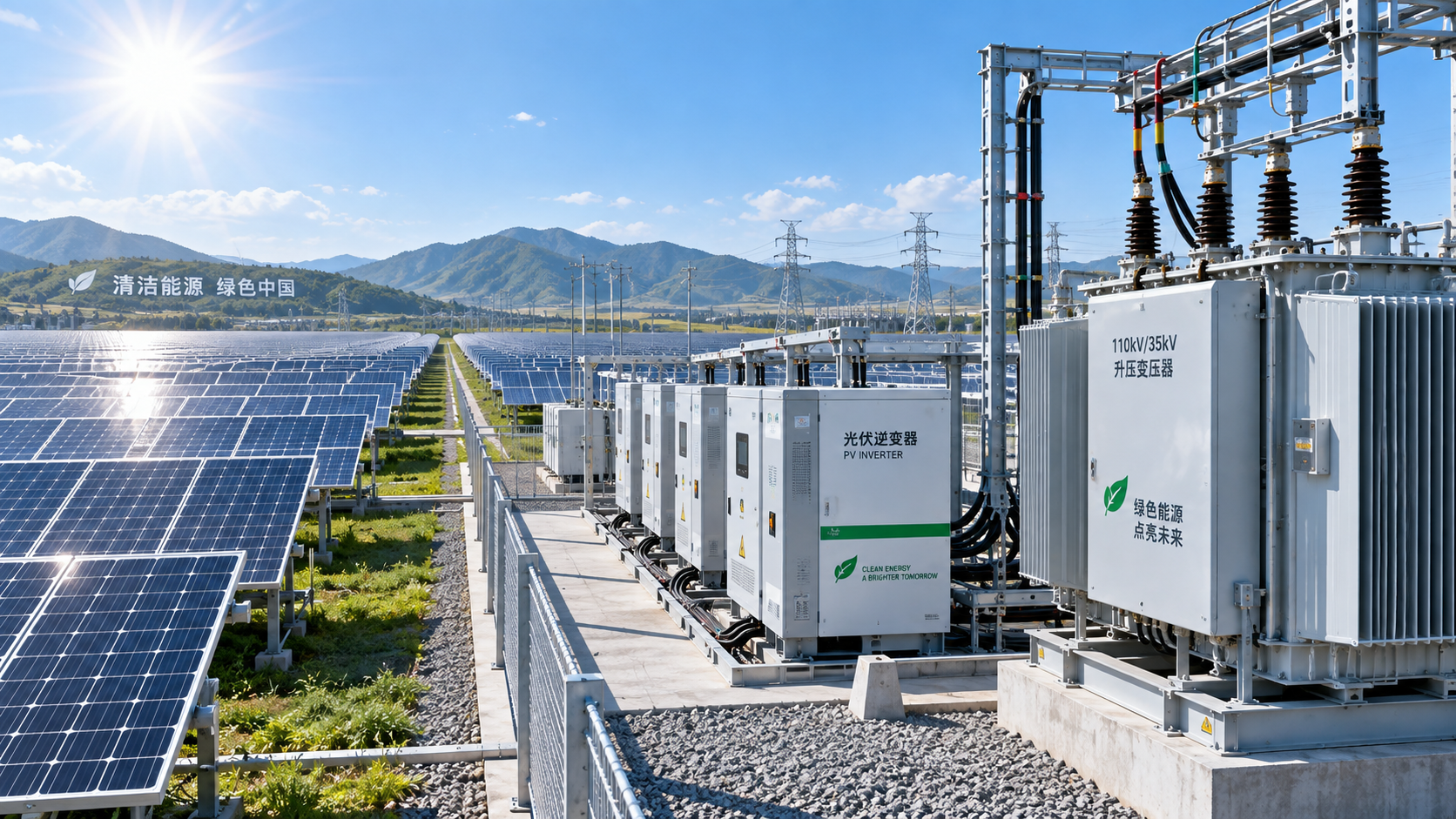
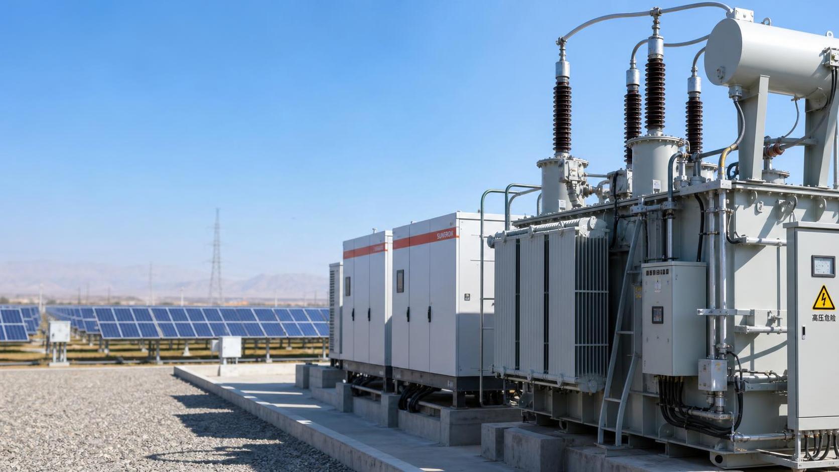
For a step-up transformer serving a solar plant, the primary calculation normally begins with the maximum AC power that the inverters can deliver at the point where they connect to the transformer. Convert real power to apparent power:
Apparent power (kVA) = real power (kW) / operating power factor
If a solar array has 1,000 kW of inverter AC output and the connection requires operation at 0.95 power factor, the transformer loading associated with that output is about 1,053 kVA. The transformer must carry apparent power, not only active kW. Where inverters are configured to provide reactive power for voltage control, the required kVA can increase even when active generation is unchanged.
Use the operating condition that places the greatest demand on the transformer. This is not always peak sunlight at unity power factor. A plant may export less active power while absorbing or supplying substantial reactive power in response to a voltage-control setting. The relevant case is the highest resulting apparent power at the transformer terminals, including losses and auxiliary loads where they are on the same side of the transformer.
For an existing distribution transformer, calculate net loading in both directions. During low solar production, the transformer may serve facility demand in its original direction. During high generation and low site demand, power reverses toward the grid. Both cases need review because transformer thermal loading may be acceptable while protective devices, metering, or voltage regulation arrangements are unsuitable for reverse power flow.
Read the nameplate as an operating limit, not a single number
The rated kVA or MVA is essential, but it is only one part of the answer. Record the high-voltage and low-voltage ratings, vector group, impedance percentage, cooling class, frequency, insulation level, tap range, temperature-rise information, and any stated altitude or ambient limitations. Confirm whether the rating applies to natural air cooling, forced-air cooling, or another cooling stage. A transformer marked with multiple ratings may require fans or other equipment to be operational before the higher rating is available.
Also establish whether the nameplate rating is a continuous rating under stated reference conditions. High ambient temperature, poor ventilation, blocked radiators, direct solar exposure on an outdoor enclosure, or a restricted transformer room can reduce usable thermal margin. The issue is especially relevant when commissioning occurs in mild weather but full export will occur during hotter months.
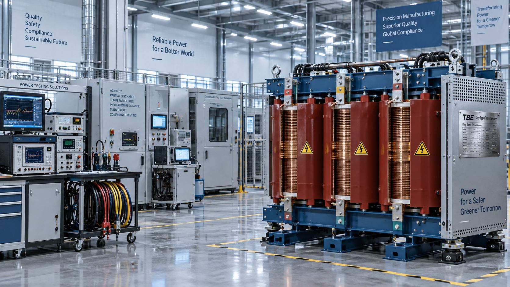
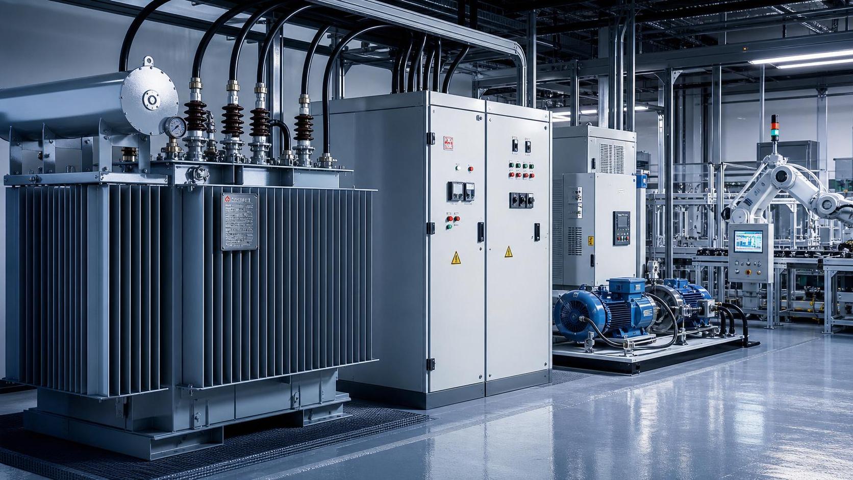
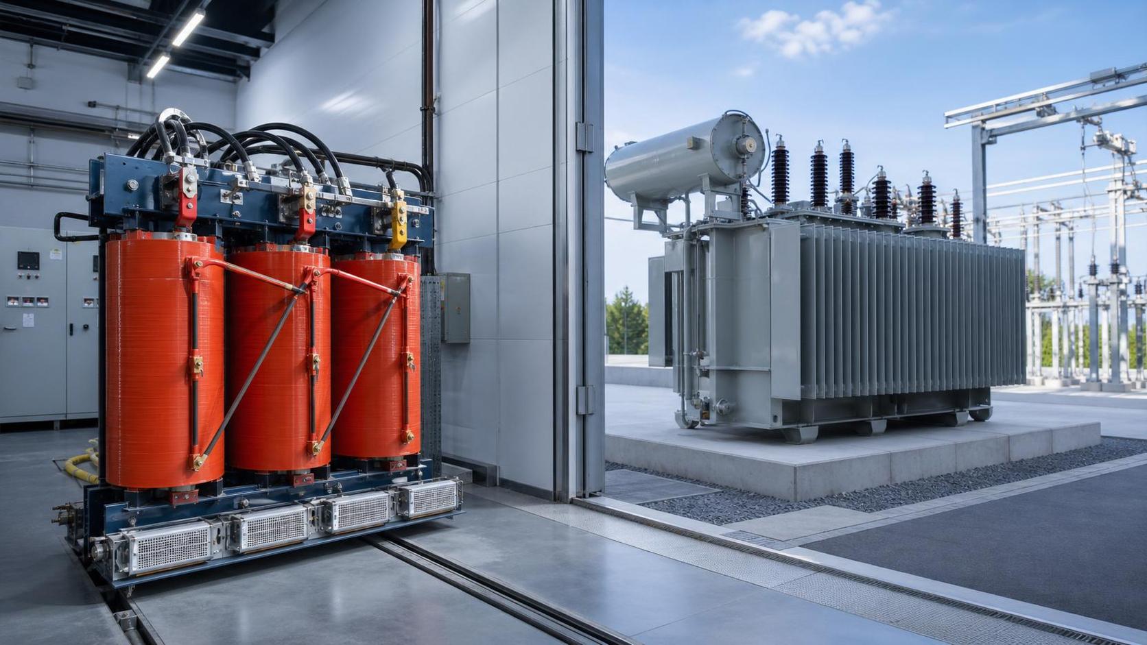
Oil-filled units require a physical review of radiator condition, oil level, fan operation where fitted, gauges, pressure-relief devices, cable-box seals, and signs of leaks or overheating. For dry-type transformers, inspect winding cleanliness, enclosure ventilation, fan operation, filter condition, and evidence of moisture or dust accumulation. These observations do not replace electrical testing, but they affect whether the nameplate capacity is realistically available.
Separate transformer capacity from inverter capacity
DC module capacity is not the transformer load. Solar arrays are often sized above inverter AC capacity, so using total module MWp to select or judge a transformer can overstate the continuous AC loading. Conversely, using only the nominal inverter kW can understate loading when reactive power support is required or when the inverter’s kVA capability exceeds its active-power setting.
Review the inverter output specification for maximum continuous kVA, permitted power-factor range, current limit, and the control mode planned for commissioning. A fleet of inverters configured for volt-var control may operate differently from a plant held at fixed unity power factor. Confirm the setting to be used at the point of common coupling rather than assuming the factory default remains active.
Test voltage behavior before accepting the loading result
A transformer can have enough thermal capacity and still prevent successful energization if the voltage ratio or tap setting is wrong for solar export. Power flowing from the low-voltage side toward the high-voltage system can raise voltage at the inverter terminals and at the point of connection. Cable impedance, transformer impedance, feeder length, and the strength of the upstream network all influence the result.
Compare the expected no-load and full-export voltages with inverter operating limits, transformer tap positions, and the required voltage at the grid connection. Perform this review for the actual cable lengths and conductor sizes installed. A cable substitution, an added joint, or a route change can alter voltage drop enough to matter on a low-voltage collector system.
Do not change transformer taps simply to correct a high reading measured on a sunny day. First verify meter scaling, measurement location, inverter voltage-control settings, and the upstream network voltage. A tap change affects all operating conditions. Lowering the secondary voltage may reduce export-time voltage rise but create an unacceptable low-voltage condition when generation is absent and site load is high.
Transformer impedance deserves the same care. A higher impedance generally reduces fault current and produces more voltage change under load; a lower impedance can increase prospective fault current beyond the interrupting duty of downstream equipment. Replacing a transformer with one of the same MVA rating but a different impedance can therefore require revisions to protection and switchgear assessments.
Confirm that reverse power flow is allowed through the whole path
Solar commissioning often exposes equipment that was installed for one-way supply. Review the transformer, medium-voltage switchgear, low-voltage main board, meters, protection relays, current transformers, and any export-limiting controller as a connected system. A transformer itself generally carries power in either direction when operated within its ratings, but associated protection and controls may not be arranged to do so.
Particular attention is needed where a site has an older demand meter, directional overcurrent protection, transformer differential protection, or a relay scheme based on assumed load direction. CT polarity errors can remain unnoticed during conventional load operation and become visible when solar generation reverses the measured current. Incorrect polarity may cause false power readings, failed anti-islanding tests, unstable export control, or a relay trip.
Verify the vector group against the single-line diagram and inverter interconnection design. Phase displacement, neutral availability, and earthing method affect relay connections and fault behavior. A delta-wye transformer may block certain zero-sequence current paths, while the grounded-wye side establishes the reference for ground-fault protection. These characteristics must match the protection study and the installed relay settings; they cannot be inferred safely from the transformer capacity alone.
Look beyond steady-state kVA
Commissioning tests involve energization, synchronization, power ramps, and control transitions. Transformer inrush current can be substantial when the unit is energized, particularly if residual flux and switching point align unfavorably. Ensure that upstream protection has been assessed for energization inrush and that differential protection, if installed, has the appropriate restraint or blocking arrangement. An inrush-related trip does not prove the transformer is undersized, but it does show that the energization scheme or protection settings need attention.
Harmonic loading is another condition that deserves a specific review rather than a generic assumption. Modern inverters are designed to limit harmonic output, yet the combined result at a transformer depends on inverter filters, network impedance, cable arrangement, background distortion, and operating mode. Harmonic current creates additional heating, especially where higher-frequency components increase winding and eddy-current losses. If the connection assessment specifies distortion limits or a harmonic study, confirm that the installed inverter configuration and transformer rating align with that assessment.
Where battery storage, large motor loads, electric vehicle charging, or a generator also connect through the transformer, model the combined operating states. A transformer adequate for solar export by itself may be overloaded when storage charges during low generation or when a generator and solar source overlap during a transfer sequence. Treat each credible dispatch state separately rather than adding all nameplate values without regard to control logic.
Use field measurements to validate the documents
Before first export, compare installed equipment labels with drawings and record the actual tap position. Confirm phase rotation, voltage ratio, grounding continuity, insulation resistance results where applicable, and transformer test records required by the project specification. Verify torque records for terminations, because a loose high-current connection can create localized heating that resembles transformer overload.
During controlled commissioning, trend three-phase voltage, current, kW, kVAr, kVA, frequency, power factor, transformer temperature indicators, and export at the connection point. Capture readings at several power levels, not only at a single full-output moment. Uneven phase currents may indicate unequal inverter allocation, a conductor issue, an incorrect CT connection, or a voltage imbalance rather than a capacity shortage.
Thermal imaging is useful after the system has stabilized under meaningful load. Compare phase terminations, bushings, cable lugs, radiator sections, enclosure vents, and switchgear connections. Interpret a hot point against its phase current and ambient conditions. A warmer terminal carrying substantially more current is not the same finding as a hot terminal with similar current to adjacent phases; the latter calls for closer investigation of connection resistance or contact condition.
Handle future expansion without hiding present constraints
If later solar blocks are planned, reserve capacity using the same kVA and voltage analysis rather than simply subtracting current kW from the transformer nameplate. Future inverters may have a different power-factor capability, and a larger collector circuit may alter voltage rise and protection settings. Document the unused thermal margin, the assumed reactive-power range, available tap range, feeder limitations, and switchgear fault-duty limits.
Where capacity is marginal, options may include reducing inverter apparent-power output through controls, revising reactive-power settings, limiting export, improving cooling only where the transformer design permits it, installing a parallel or larger transformer, or changing the interconnection arrangement. The suitable remedy depends on the actual constraint. Curtailment addresses steady-state export loading, for example, but it does not correct inadequate fault-duty ratings or a reverse-power protection problem.
Release the transformer for normal operation only after the calculated loading envelope, installed configuration, protection behavior, and measured commissioning results agree. That evidence is more reliable than a single nameplate comparison and provides a clear basis for diagnosing later alarms, upgrades, or changes in operating mode.
Technical Specifications
- When are low modulus silicone sealants needed for moving joints?Author :Chemical Industry Editorial Team
- Which flooring materials hold up best in high-traffic commercial spaces?Author :Construction Materials Editorial Team
- What to verify before selecting a transformer manufacturer in the USAAuthor :Electrical Components Editorial Team
Expert Insights

Chief Security Architect
Dr. Thorne specializes in the intersection of structural engineering and digital resilience. He has advised three G7 governments on industrial infrastructure security.
Core Sector // 01
Security & Safety
- What to verify before selecting a transformer manufacturer in the USAAuthor :Electrical Components Editorial Team

- How to check transformer capacity for a solar system before commissioningAuthor :Electrical Components Editorial Team

- How to size solar transformer capacity for peak generationAuthor :Electrical Components Editorial Team

- Which solar transformer specifications must match inverter output?Author :Electrical Components Editorial Team

- How do you size a transformer for solar power projects?Author :Electrical Components Editorial Team

- How Transformers Affect Power Stability in Industrial FacilitiesAuthor :Electrical Components Editorial Team

- Dry-Type vs Oil-Filled Transformers: Which Fits Your Project?Author :Electrical Components Editorial Team