How do you size a transformer for solar power projects?
Author
Date Published
Reading Time
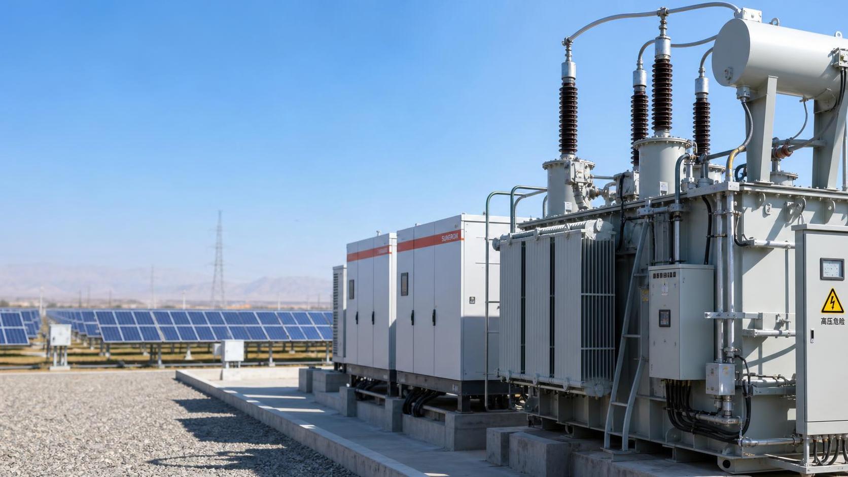
A transformer for a solar power project should be sized from the maximum continuous AC power that the inverter system can export, not simply from the PV module nameplate rating. The correct rating must also accommodate inverter power factor, voltage transformation, site temperature, harmonics, utility requirements, protection coordination, and any credible expansion plan.
The practical mistake is to begin with MWp and select an apparently equivalent MVA transformer. PV DC capacity, inverter AC capacity, and transformer continuous capacity are related, but they are not interchangeable. A 10 MWp solar array may have 8 MW, 9 MW, or 10 MW of installed inverter output depending on the DC/AC ratio. The transformer must be evaluated against the inverter plant’s AC export capability and the grid interconnection conditions.
Start with the inverter AC rating, not the PV DC rating
The first sizing input is the aggregate rated AC output of the inverters connected to one transformer. For a central-inverter block, this may be straightforward: several inverter stations feed one medium-voltage transformer. In a string-inverter design, the calculation is based on the total AC output of all inverters assigned to a transformer skid or collector section.
PV module capacity is expressed in MWp under standard test conditions. It indicates DC generation potential, but it does not define the maximum apparent power delivered to the transformer. The inverter fleet determines the AC export ceiling.
For example, a project may contain 12 MWp of modules and 10 MW of inverter capacity. If the inverters are allowed to operate at unity power factor, their maximum apparent power is approximately 10 MVA. If the grid operator requires the plant to supply or absorb reactive power while maintaining full active-power output, the apparent-power requirement can be higher.
The basic relationship is:
Transformer MVA requirement = Maximum active power (MW) ÷ Required operating power factor
Where the power factor is expressed as a decimal. At 1.00 power factor, 10 MW requires 10 MVA. At 0.95 power factor, the same 10 MW requires:
10 MW ÷ 0.95 = 10.53 MVA
This calculation is only valid if the inverter system can actually deliver 10 MW while providing the required reactive power. Many modern inverters have a defined MVA limit: once reactive power increases, active power may need to be curtailed unless the inverter was oversized. The transformer, inverter capability curve, and interconnection agreement must therefore be checked together rather than treated as separate design decisions.
Establish the real maximum operating point
Transformer sizing should reflect the most demanding credible operating condition, which is not always the annual peak energy period. The key question is: what combination of active power, reactive power, voltage, ambient temperature, and harmonic loading can occur continuously under the project’s contractual and grid-code obligations?
For a grid-connected plant, the design team should identify whether the point of interconnection requires:
- operation at a specified power factor, such as 0.95 leading or lagging;
- reactive-power control over a defined active-power range;
- voltage regulation or Volt-VAR control;
- reactive power availability at full plant output;
- temporary overload capability during grid support events;
- active-power curtailment under high grid voltage or utility dispatch instructions.
A transformer selected solely for nominal MW output may become a restriction when the plant is instructed to provide VAR support. That restriction can be commercially significant if the plant must either curtail active generation or fail to meet an interconnection obligation.
It is equally important to distinguish continuous operation from short-duration events. A transformer may tolerate a temporary overload depending on its thermal design, cooling arrangement, ambient conditions, and manufacturer documentation. That does not mean its nameplate rating can be reduced on the assumption that peak solar output is brief. In high-irradiance locations, near-maximum inverter output can persist long enough for thermal loading to matter, especially when high ambient temperature reduces cooling margin.
Choose a rating with a defensible margin, not an arbitrary oversized unit
After calculating the required MVA, a margin is normally considered for operating uncertainty, site conditions, and future changes. The margin should be tied to a specific reason. Adding capacity without defining the reason can increase capital cost, no-load losses, footprint, and procurement lead time without improving project performance.
Reasons that may justify additional transformer capacity include:
- planned addition of inverter blocks, battery storage, or another generation source;
- utility requirements that reserve reactive-power capacity beyond the initial operating schedule;
- high ambient temperature, altitude, restricted ventilation, or an enclosure that affects cooling;
- known harmonic loading that requires derating or a transformer designed for non-sinusoidal current;
- a preferred standard MVA rating that provides an efficient step above the calculated requirement;
- expected changes in the plant controller or grid code during the operating life of the asset.
Future expansion deserves separate treatment. A transformer cannot be assumed to support additional PV modules merely because the DC field is expanded. If inverter AC capacity remains unchanged, extra DC capacity may increase clipping rather than transformer loading. If additional inverters are installed, the transformer, medium-voltage collector cables, switchgear, protection settings, and interconnection limit all need review.
Oversizing also has an energy implication. Transformer no-load losses occur whenever the transformer is energized, including at night. Load losses rise with current and are influenced by winding resistance. The lowest purchase price or the largest nameplate rating is not automatically the lowest lifetime-cost option. Loss capitalization requirements in the project specifications or utility tender documents should be reviewed before comparing bids.
Voltage ratio is a system decision, not just a nameplate field
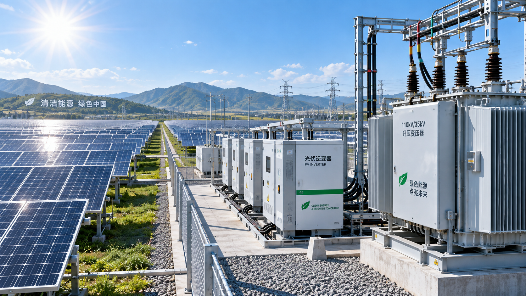
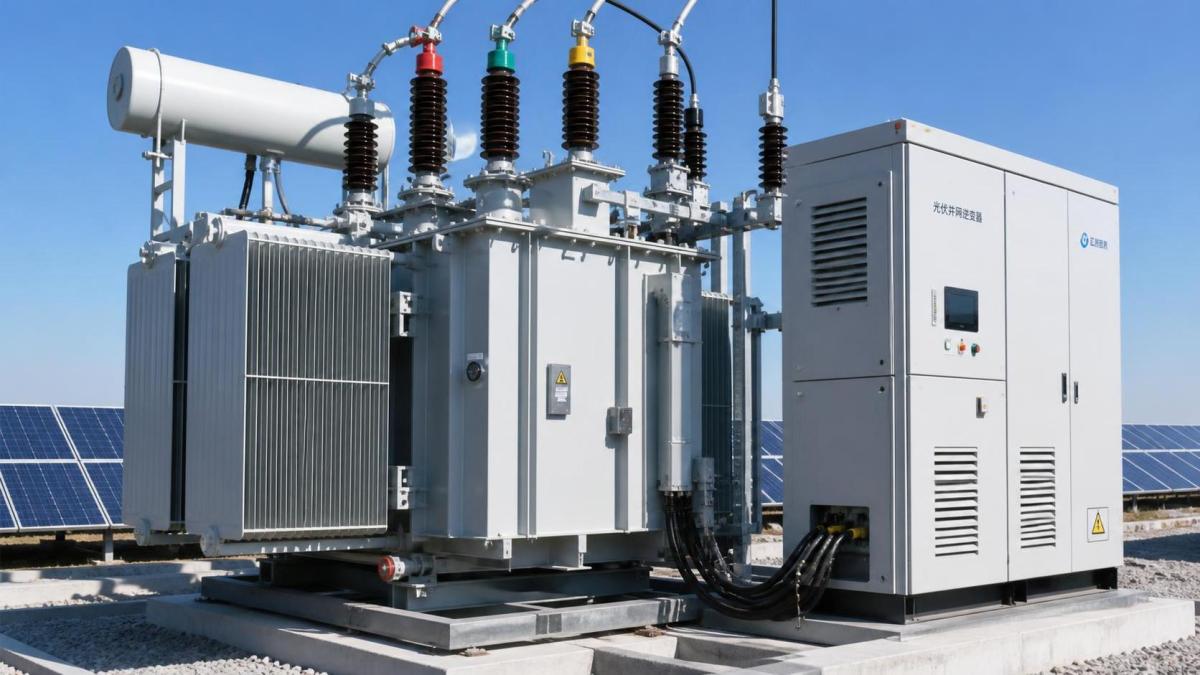
The voltage ratio must match the inverter output voltage and the collector or grid voltage at the relevant connection point. Inverter output is commonly low voltage, while collector systems operate at medium voltage before power is stepped up again at a substation for transmission or distribution interconnection.
A solar project may use:
- a low-voltage to medium-voltage inverter step-up transformer;
- a medium-voltage collector transformer at a substation;
- both, in larger plants with multiple voltage levels.
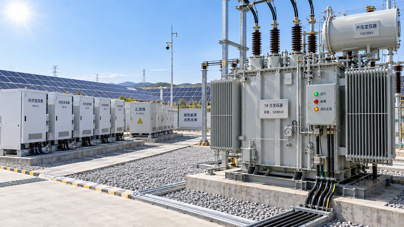
Each transformer must be sized for its own loading and system duty. The inverter step-up unit handles the output of a defined inverter block. The main transformer aggregates power from the collector system and may see the full plant export capacity, auxiliary loads, reactive-power flows, and any battery connection on the same bus.
Nominal voltage alone is insufficient. The specified ratio must reflect permissible voltage variation, tap range, tap changer arrangement, inverter voltage limits, cable voltage drop, and the utility’s required voltage at the point of interconnection. A transformer that appears correct at nominal voltage can create inverter operating constraints if the low-voltage winding voltage is not coordinated with the full operating range of the collection circuit.
Off-circuit taps may be adequate where the voltage profile is stable and adjustments are made only during commissioning or planned outages. On-load tap changers are more complex and costly but may be required where voltage regulation duties, grid conditions, or connection requirements demand active adjustment. The choice should follow a power-flow and voltage-control study, not a default preference.
Calculate current early because it drives the rest of the equipment
Transformer MVA determines current at each voltage level. These current values affect cable sizing, busbars, switchgear ratings, circuit breakers, protection transformers, and connector arrangements.
For a three-phase system:
Line current (A) = Apparent power (VA) ÷ (√3 × Line-to-line voltage (V))
Consider a 10.5 MVA transformer with a 33 kV high-voltage winding and an 800 V low-voltage winding:
- At 33 kV, current is approximately 184 A.
- At 800 V, current is approximately 7,578 A.
The high low-voltage current explains why transformer placement, low-voltage bus design, inverter grouping, and cable routing are important in solar block layouts. Long low-voltage cable runs create higher losses and voltage drop. Locating the transformer near the inverters can reduce low-voltage collection losses, although it may increase the amount of medium-voltage cabling and influence maintenance access and civil works.
Account for inverter harmonics and waveform-related heating
Inverters do not produce a perfectly sinusoidal current waveform. Their switching characteristics and control settings can introduce harmonic components, even though compliant equipment is designed to keep distortion within specified limits. Harmonic current causes additional eddy-current and stray losses in transformer windings and structural parts, which can increase heating beyond that predicted by a simple fundamental-frequency load calculation.
The relevant question is not whether harmonics exist, but whether the transformer has been designed and rated for the actual harmonic spectrum and loading profile. The inverter manufacturer should provide harmonic-current data at relevant operating points. The transformer supplier should then confirm the design basis, losses, temperature-rise assumptions, and any derating requirement.
Do not accept a generic statement that a transformer is “suitable for solar” without identifying the required technical evidence. The project specification should state the inverter technology, number of units, expected harmonic performance, voltage level, grounding arrangement, and applicable standard. IEC 60076 is widely used for power transformers, while IEEE C57 series requirements may apply in projects governed by North American practice. The governing utility specification and local electrical code remain controlling where they impose additional conditions.
Grounding and vector group can decide whether the plant operates reliably
Transformer vector group and neutral grounding arrangement directly affect fault detection, protection coordination, and inverter behavior during unbalanced faults. They should not be left as a late procurement detail.
A delta winding can block zero-sequence current between sides of the transformer, while a grounded-wye winding provides a neutral reference and can support earth-fault protection. The appropriate configuration depends on the inverter output arrangement, collector-system grounding method, utility fault-level requirements, protection philosophy, and whether the transformer is part of a grounded or impedance-grounded medium-voltage network.
Incorrect assumptions can lead to nuisance tripping, insufficient earth-fault current for protection operation, unacceptable overvoltages during ground faults, or incompatibility with the utility’s protection scheme. Vector group selection should be confirmed through the protection study and not simply copied from another project with a different grid connection.
Short-circuit strength and impedance require coordination
Transformer impedance controls both voltage regulation and fault current. Lower impedance can improve voltage performance but increases available short-circuit current. Higher impedance limits fault current but creates greater voltage drop under load and reactive-power flow.
There is no universally correct impedance value for a transformer for solar power. It must fit the collector system, breaker interrupting ratings, cable impedance, inverter fault-current contribution, protection settings, and utility fault-level study. Inverter-based resources generally contribute fault current differently from synchronous generators, often with controlled and limited current magnitude. Protection design must use the actual inverter fault-response characteristics rather than assumptions developed for conventional generation.
Specification review should verify that the selected transformer impedance is reflected consistently in the load-flow, short-circuit, arc-flash, and protection coordination studies. A change in transformer impedance after these studies are complete can require revisions to multiple project packages.
Site conditions can change the usable rating
Transformer nameplate capacity is linked to defined cooling and ambient conditions. A unit installed in a hot, dusty, high-altitude, coastal, or enclosed environment may need a modified design or derated operation.
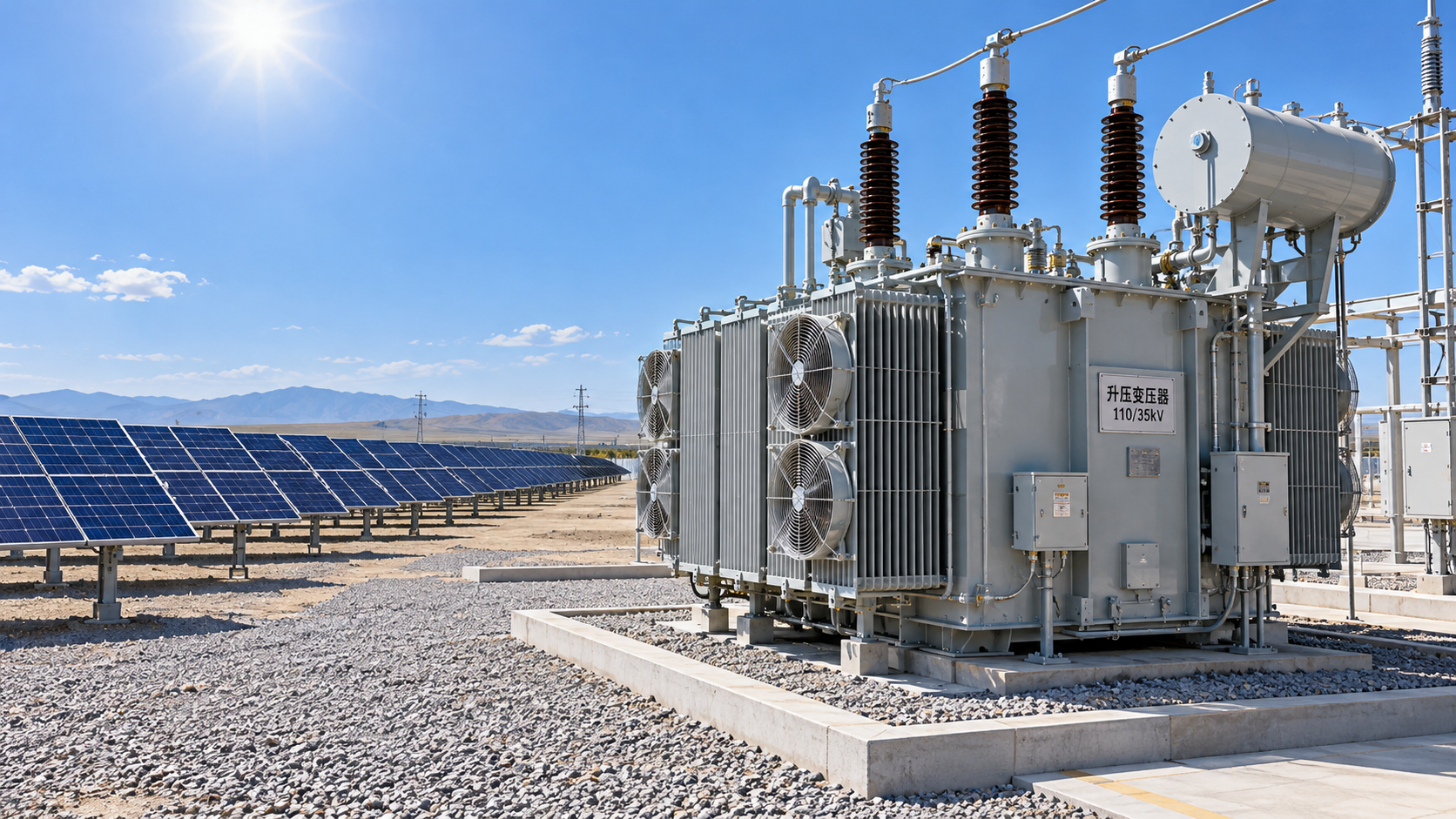
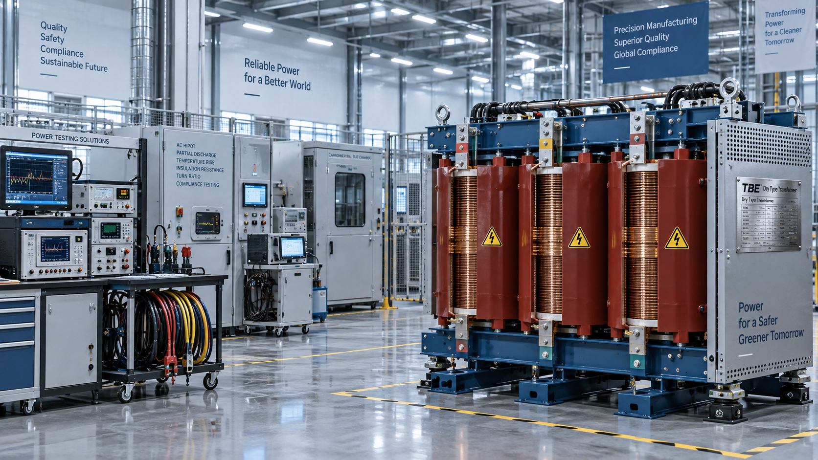
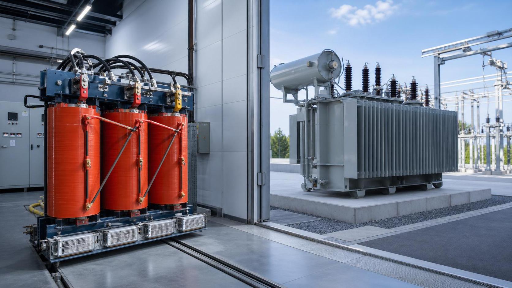
Oil-filled transformers require attention to fire separation, oil containment, access for inspection, and environmental controls. Dry-type transformers avoid insulating liquid but can be sensitive to ventilation, enclosure temperature, contamination, and noise constraints. Neither construction is inherently better for every solar site. The choice depends on location, fire rules, maintenance capability, environmental permitting, transport limitations, and the required voltage and MVA rating.
For outdoor installations, the specification should address corrosion class, solar radiation, wind loading, ingress protection for associated enclosures, seismic requirements where applicable, and the availability of safe lifting and replacement access. These conditions affect both technical suitability and construction scheduling.
A workable sizing example
Assume a solar plant has 24 inverter stations, each rated at 250 kW AC. Six stations feed each transformer, creating four identical inverter blocks.
Each block has:
6 × 250 kW = 1.5 MW AC
If the grid agreement requires operation at 0.95 power factor at full active output, the apparent-power demand per block is:
1.5 MW ÷ 0.95 = 1.58 MVA
A 1.6 MVA transformer might appear sufficient, but the decision should still test ambient temperature, transformer loss requirements, harmonic design, permitted overload, future inverter additions, and the availability of standard ratings. A 2 MVA unit may be justified if the project includes a defined expansion or demanding thermal conditions. It is not justified merely because larger capacity feels safer.
If the inverter control system limits active output when reactive demand rises, the operating analysis may show that 1.6 MVA is adequate. If the project must sustain 1.5 MW and the full reactive requirement simultaneously, the transformer and inverter MVA capabilities must both support that point.
What should be fixed before procurement
A transformer data sheet should not be issued with only MVA and voltage ratio. At minimum, it should align the continuous rating, voltage range, frequency, vector group, impedance, tap arrangement, insulation and temperature-rise requirements, cooling method, loss evaluation method, harmonic duty, grounding arrangement, short-circuit withstand level, terminal configuration, monitoring devices, environmental conditions, applicable standards, testing requirements, and utility-specific obligations.
The most reliable selection process is to freeze the transformer rating only after the inverter schedule, grid code, power-flow study, reactive-power strategy, protection study, and site environmental basis are sufficiently mature. A transformer is not merely a voltage-conversion device in a solar project. It is the point where inverter capability, grid compliance, thermal limits, protection behavior, and lifetime losses become one engineering decision.
Technical Specifications
- How to verify Global Industrial Insights sourcing informationAuthor :Industrial Machinery Editorial Team
- Which thermoplastic elastomers stay flexible at low temperatures?Author :Polymers & Rubber Editorial Team
- Which Shore hardness suits soft touch TPE for handheld grips?Author :Polymers & Rubber Editorial Team
Expert Insights

Chief Security Architect
Dr. Thorne specializes in the intersection of structural engineering and digital resilience. He has advised three G7 governments on industrial infrastructure security.
Core Sector // 01
Security & Safety
- How ambient temperature affects solar transformer specificationsAuthor :Electrical Components Editorial Team

- What to verify before selecting a transformer manufacturer in the USAAuthor :Electrical Components Editorial Team

- How to check transformer capacity for a solar system before commissioningAuthor :Electrical Components Editorial Team

- How to size solar transformer capacity for peak generationAuthor :Electrical Components Editorial Team

- Which solar transformer specifications must match inverter output?Author :Electrical Components Editorial Team

- How do you size a transformer for solar power projects?Author :Electrical Components Editorial Team

- How Transformers Affect Power Stability in Industrial FacilitiesAuthor :Electrical Components Editorial Team

- Dry-Type vs Oil-Filled Transformers: Which Fits Your Project?Author :Electrical Components Editorial Team