How to size solar transformer capacity for peak generation
Author
Date Published
Reading Time
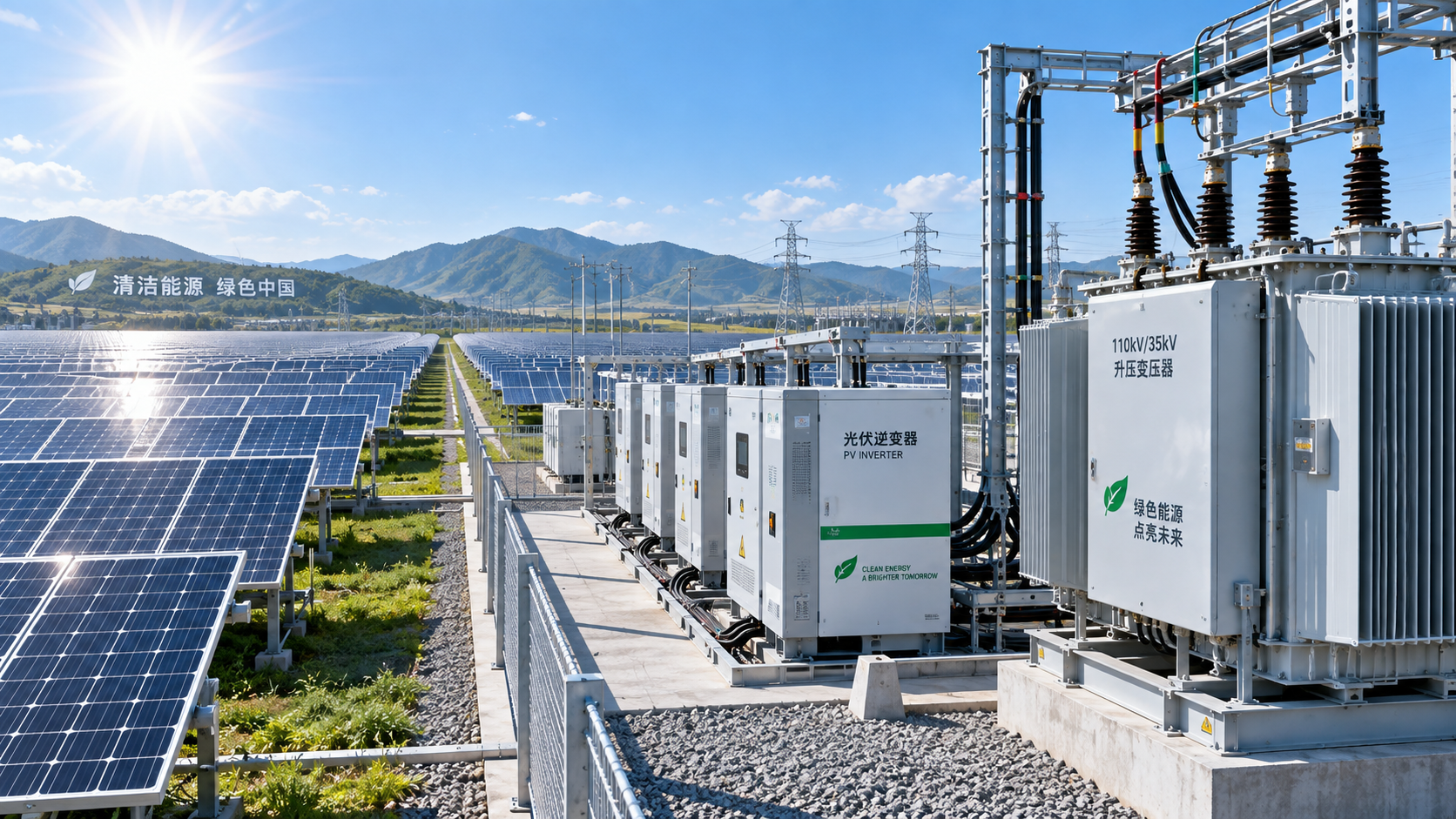
How to Size Solar Transformer Capacity for Peak Generation
Sizing a solar transformer is often treated as a simple conversion from MW to MVA. That shortcut can work only when the inverter operating range, required power factor, ambient conditions, grid obligations, and future operating strategy are already understood. In real utility-scale and commercial solar projects, they rarely are.
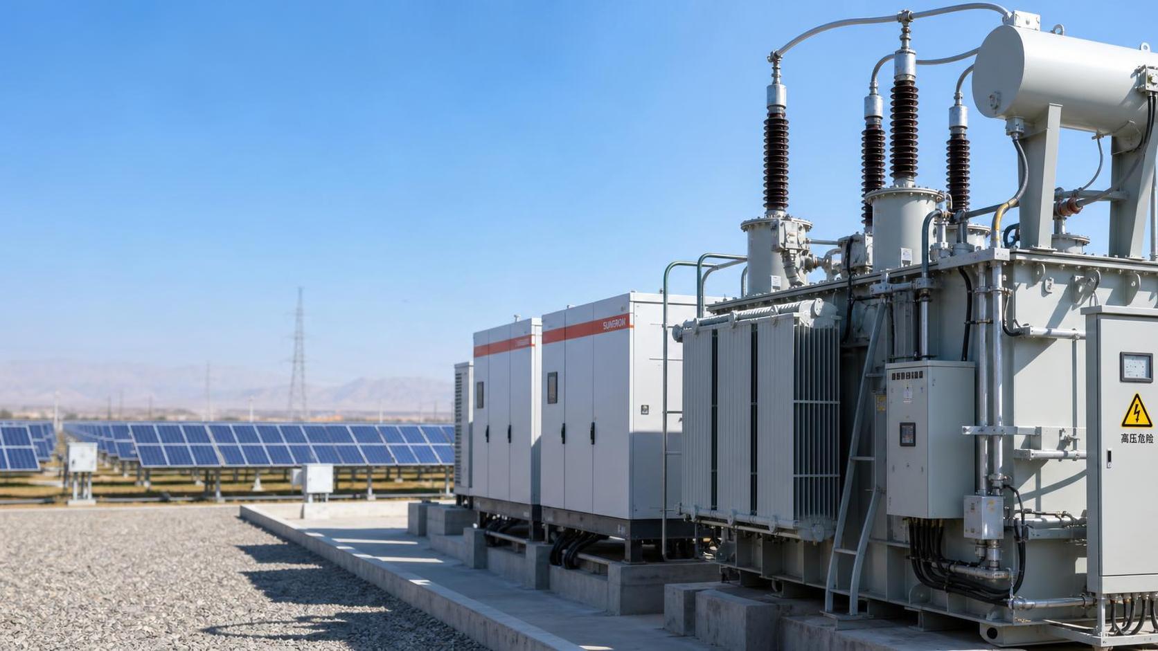
The transformer sits between the inverter blocks and the medium- or high-voltage grid connection point. Its rating must accommodate the maximum apparent power that may pass through it, not merely the expected annual energy output or the DC nameplate capacity of the PV modules. A transformer that is too small can impose curtailment, raise thermal stress, and complicate grid-code compliance. One that is oversized may add avoidable capital cost, no-load losses, transport complexity, and installation constraints.
For technical evaluations, the central question is not “How many megawatts is the solar plant?” It is: What is the highest sustained and short-duration apparent-power duty the transformer must carry under the project’s actual operating conditions?
Start with AC inverter output, not DC module capacity
PV module capacity is usually expressed in MWp on the DC side. Transformer capacity, however, is normally specified in kVA or MVA and is governed by AC-side loading. The first reference point should therefore be the combined rated AC output of the inverters connected to a transformer block.
A plant may have a DC/AC ratio above 1.0, meaning the module field has more DC capacity than the inverters can export at their nominal AC rating. This is common because it improves energy capture during lower-irradiance periods. It does not automatically mean the transformer must be sized for the full DC array rating. If a 100 MWp DC field feeds inverters rated at 80 MW AC, the transformer’s base loading assessment begins with the 80 MW AC inverter limit, subject to reactive-power requirements and other factors discussed below.
This distinction matters when reviewing project documents from different parties. Module suppliers may discuss MWp, inverter suppliers may quote MW and MVA, while transformer manufacturers need a defined MVA duty, voltage ratio, frequency, vector group, cooling class, impedance target, and site conditions. A capacity calculation can look correct while still being based on mismatched definitions.
Convert real power into the apparent power the transformer carries
Transformers are thermally limited by current, and current follows apparent power rather than active power alone. The basic relationship is:
Required transformer MVA = Maximum active power in MW ÷ operating power factor
At unity power factor, 1 MW corresponds to 1 MVA. When the plant must provide or absorb reactive power, the power factor moves below 1.0 and apparent power rises. For example, 80 MW delivered at a power factor of 0.95 requires approximately 84.2 MVA of apparent-power capability. The exact operating requirement should be taken from the grid interconnection agreement, utility studies, inverter capability curves, and plant control philosophy rather than assumed from a generic design rule.
Reactive power is frequently the item missed in early solar transformer capacity estimates. An inverter may be capable of operating at rated MW only within a limited power-factor range. If it is asked to provide significant vars at the same time as peak real-power export, it may either need to reduce active power or operate closer to its MVA limit. The transformer must be checked against the resulting apparent-power flow, including conditions that the grid operator may call for during high generation.
A practical calculation should identify at least three operating points: maximum MW export, maximum reactive-power duty, and the combined MW-plus-Mvar condition that produces the highest MVA. The highest of those conditions is generally more useful than a single headline capacity number.
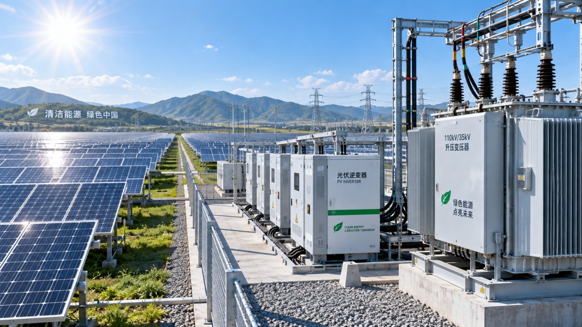
Peak generation is not always the same as peak thermal duty
A solar site can reach its maximum AC export during periods that do not create the transformer’s most severe temperature condition. Conversely, a transformer may experience difficult thermal conditions during a hot afternoon even when irradiance, and therefore active generation, is below the plant’s absolute maximum. Ambient temperature, solar loading on outdoor equipment, altitude, ventilation, and enclosure design all influence permissible loading.
Manufacturers normally state a transformer rating against defined assumptions. These assumptions need to be compared with the actual site design. A rating suitable for a temperate location may require derating in a high-temperature desert environment, at elevated altitude, or inside a compact transformer station with restricted airflow. The relevant temperature-rise limits and cooling arrangement also affect the result.
It is tempting to argue that solar output falls as module temperature rises, reducing the need for transformer margin in hot climates. There is some operational logic in that observation, but it is not a substitute for a thermal assessment. The project must still consider inverter clipping behavior, irradiance variability, reactive-power dispatch, ambient extremes, and the loading profile expected over the asset life. A transformer supplier should receive the site temperature range and installation details early enough to confirm any correction factors.
A working sizing sequence
A disciplined sizing process is more reliable than applying a fixed percentage margin. The following sequence helps turn electrical assumptions into a procurement-ready transformer duty.
- Define the inverter block. Confirm the number of inverters, each unit’s maximum continuous AC output, its maximum MVA capability, and the intended number of operating units. Do not rely only on the plant’s total AC capacity if each transformer serves a separate block.
- Establish the grid operating envelope. Identify the required active-power export, power-factor range, reactive-power setpoints, voltage-control mode, and any specified overload or fault-related duty that affects the transformer design.
- Calculate maximum apparent power. Use the worst credible simultaneous MW and Mvar condition, while respecting inverter capability limits. This produces the electrical MVA requirement before environmental adjustments.
- Apply site and installation corrections. Review ambient temperature, altitude, cooling medium, solar exposure, station layout, and cable or busbar losses where relevant to the defined duty point.
- Decide on an intentional margin. Margin should have a stated purpose: future inverter addition, expected grid-service obligations, planned repowering, or uncertainty in early-stage design. An unexplained large margin is not the same as a resilient design.
- Validate the full electrical package. Check transformer impedance, tap range, insulation level, vector group, protection coordination, harmonic conditions, switching transients, and collector-system voltage drop. Capacity alone does not guarantee compatibility.
For a preliminary estimate, a technical evaluator may calculate the maximum inverter-block MW divided by the minimum required power factor, then discuss an appropriate design allowance with the EPC contractor, grid consultant, and transformer manufacturer. For final selection, that estimate should be replaced by a documented duty cycle and project-specific specification.
Where margins help—and where they hide unresolved design questions
Some margin is often justified, but “add 10%” is not a universal answer. The appropriate allowance depends on whether the transformer is a central plant step-up unit, a pad-mounted inverter transformer, or part of a skid-mounted power station. It also depends on whether the project intends to add PV capacity, replace inverters with higher-output units, or participate in reactive-power and voltage-support programs later.
Oversizing can also create trade-offs that are overlooked in budget discussions. A larger transformer may have higher no-load losses, especially relevant because it remains energized outside production hours. It may require a larger foundation, wider transport access, higher lifting capacity, or different protection settings. The best rating is therefore not simply the highest rating a budget can accept; it is the rating that satisfies the verified duty with an explicit, defensible reserve.
Do not separate capacity from voltage regulation and impedance
A correctly sized MVA rating can still lead to operational issues if voltage ratio, tap arrangement, or impedance is poorly matched to the collector system and point of interconnection. Solar output changes rapidly with irradiance, and inverter controls may respond to voltage conditions across multiple feeder blocks. Transformer impedance affects voltage drop, fault current, parallel operation, and the way inverter stations interact with the network.
Tap selection deserves particular attention. The appropriate nominal ratio depends on the inverter output voltage, collector voltage, expected cable drop, utility voltage tolerance, and the available tap configuration. Whether off-circuit taps or on-load tap changing is appropriate depends on the system architecture and the local grid requirement; it should not be decided from capacity alone.
Harmonics are another point for coordination. Modern inverters are designed to meet applicable connection requirements, but the transformer and cable network should still be assessed as a system where harmonic limits, resonance risk, and operating modes warrant it. This becomes more relevant when the same site includes battery energy storage, capacitor banks, or other power-electronic equipment.
Common sizing errors in solar projects
The most common error is choosing transformer capacity equal to the plant’s MWac rating without checking the required power factor. A second is sizing against MWp because the DC figure is more visible in project summaries. Both approaches can produce a misleading result.
Another frequent issue is treating a manufacturer’s standard rating as automatically suitable for the site. Standard ratings are useful starting points, but project conditions may require a different cooling arrangement, insulation specification, bushing configuration, tap range, or thermal design. Delivery lead time can also affect the decision: a non-standard MVA rating may be technically attractive but less practical if the project schedule is tight. That trade-off should be visible in procurement planning rather than discovered after the electrical design is frozen.
Finally, expansion is often discussed too vaguely. If future capacity is genuinely planned, the transformer is only one part of the constraint. Switchgear, collector cables, protection relays, foundations, feeder positions, grid approvals, and interconnection rights may all limit expansion before the transformer does. Buying a larger unit without checking those boundaries may create cost without creating usable headroom.
Build the specification around a verified duty profile
The most useful transformer inquiry package contains more than a requested MVA figure. It should state the maximum and normal loading conditions, inverter data, voltage levels, frequency, required power-factor range, site ambient conditions, altitude, installation arrangement, connection configuration, expected tap requirements, applicable utility rules, and any future expansion scenario. Where the design is still changing, the uncertainty should be identified rather than buried in a generic margin.
For global buyers and project teams comparing technical information across markets, it is worth separating confirmed grid requirements from assumptions carried over from another project. Standards, utility practices, logistics constraints, and available manufacturing configurations can differ materially by destination. Reviewing market updates, supply-chain conditions, product documentation, and local connection requirements together gives a more reliable basis for sourcing than comparing price and MVA rating alone.
A sound solar transformer capacity decision begins with inverter MVA capability and the plant’s actual grid-service obligation, then tests that duty against temperature, installation, electrical coordination, and future plans. If those inputs are documented, the final rating becomes easier to defend technically—and far less likely to become an avoidable bottleneck once peak generation arrives.
Technical Specifications
- What to verify before selecting a transformer manufacturer in the USAAuthor :Electrical Components Editorial Team
- How to choose a cutting machine for stone based on slab thicknessAuthor :Construction Materials Editorial Team
- When are porcelain tiles for outdoor spaces at risk of cracking?Author :Construction Materials Editorial Team
Expert Insights

Chief Security Architect
Dr. Thorne specializes in the intersection of structural engineering and digital resilience. He has advised three G7 governments on industrial infrastructure security.
Core Sector // 01
Security & Safety
- What to verify before selecting a transformer manufacturer in the USAAuthor :Electrical Components Editorial Team

- How to size solar transformer capacity for peak generationAuthor :Electrical Components Editorial Team

- Which solar transformer specifications must match inverter output?Author :Electrical Components Editorial Team

- How do you size a transformer for solar power projects?Author :Electrical Components Editorial Team

- How Transformers Affect Power Stability in Industrial FacilitiesAuthor :Electrical Components Editorial Team

- Dry-Type vs Oil-Filled Transformers: Which Fits Your Project?Author :Electrical Components Editorial Team