Which solar transformer specifications must match inverter output?
Author
Date Published
Reading Time

Match the Transformer to the Inverter's AC Side, Not Just the Plant Nameplate
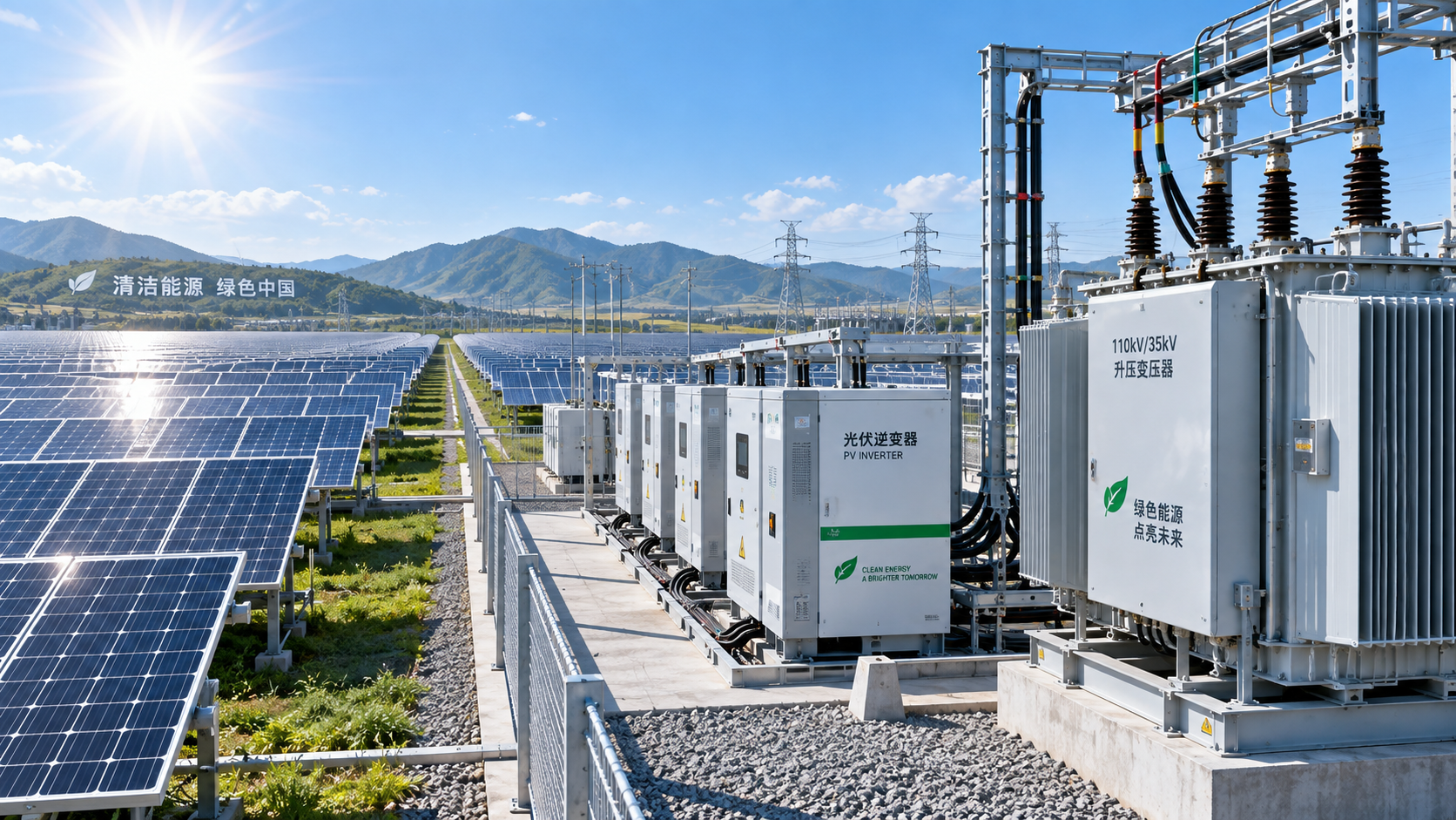
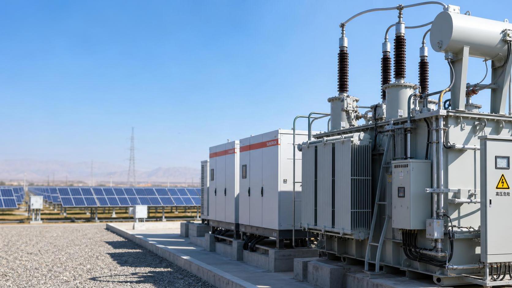
A solar transformer should be selected from the inverter's actual AC output requirements and the grid interconnection design, not simply from the MW figure printed on the project schedule. The most important specifications to match are voltage, apparent power, frequency, phase arrangement, vector group, impedance, insulation and cooling duty, and the earthing arrangement created by the transformer winding connection.
For project managers, the risk is rarely that a transformer will be obviously too small on paper. More often, the transformer is broadly rated for the plant capacity but does not suit the inverter's voltage tolerance, harmonic profile, overload behavior, or protection philosophy. Those mismatches can emerge during factory acceptance testing, grid-code review, energization, or the first periods of high irradiation. Correcting them late can delay commissioning and create expensive changes to cabling, protection settings, switchgear, or the transformer itself.
The useful starting point is the inverter data sheet for the exact operating configuration, then the electrical single-line diagram. A preliminary transformer selection made before inverter output voltage, block size, grounding concept, and utility requirements are fixed should be treated as provisional.
Voltage Matching Is More Than a Nominal Ratio
The transformer low-voltage winding must match the inverter's AC output voltage and the range over which the inverter is designed to operate. This sounds straightforward, but nominal labels can hide an important distinction. An inverter may be described as a 400 V, 480 V, 690 V, or 800 V class unit, while its permitted output-voltage window and control behavior vary with grid conditions, reactive-power dispatch, temperature, and loading.
The transformer ratio must allow the inverter to remain within that permitted window at the point where the inverter sees voltage. Cable voltage drop between inverter and transformer, transformer impedance, tap position, and medium-voltage grid variation all affect that result. A design that works at nominal voltage can still push the inverter toward a voltage limit when the plant is exporting reactive power or when the collector system is lightly loaded.
Project teams should request the inverter manufacturer’s rated AC voltage, allowable continuous voltage range, maximum voltage, and applicable derating conditions. These values should be assessed against the transformer’s low-voltage rating and tap arrangement. The transformer high-voltage side must then align with the collector voltage and the permitted voltage range at the point of interconnection.
Tap changers require a practical decision rather than a default specification. Many inverter step-up transformers use off-circuit taps because the collector system is designed around a relatively stable voltage plan. Where the grid or collector voltage can vary materially, the tap range and selected nominal tap should be evaluated during power-flow studies. Adding an on-load tap changer may solve a real voltage-control problem in some systems, but it also adds cost, controls, maintenance obligations, and protection coordination work. It should not be treated as an automatic feature of a solar transformer specification.
Use MVA, Not MW, to Size the Transformer
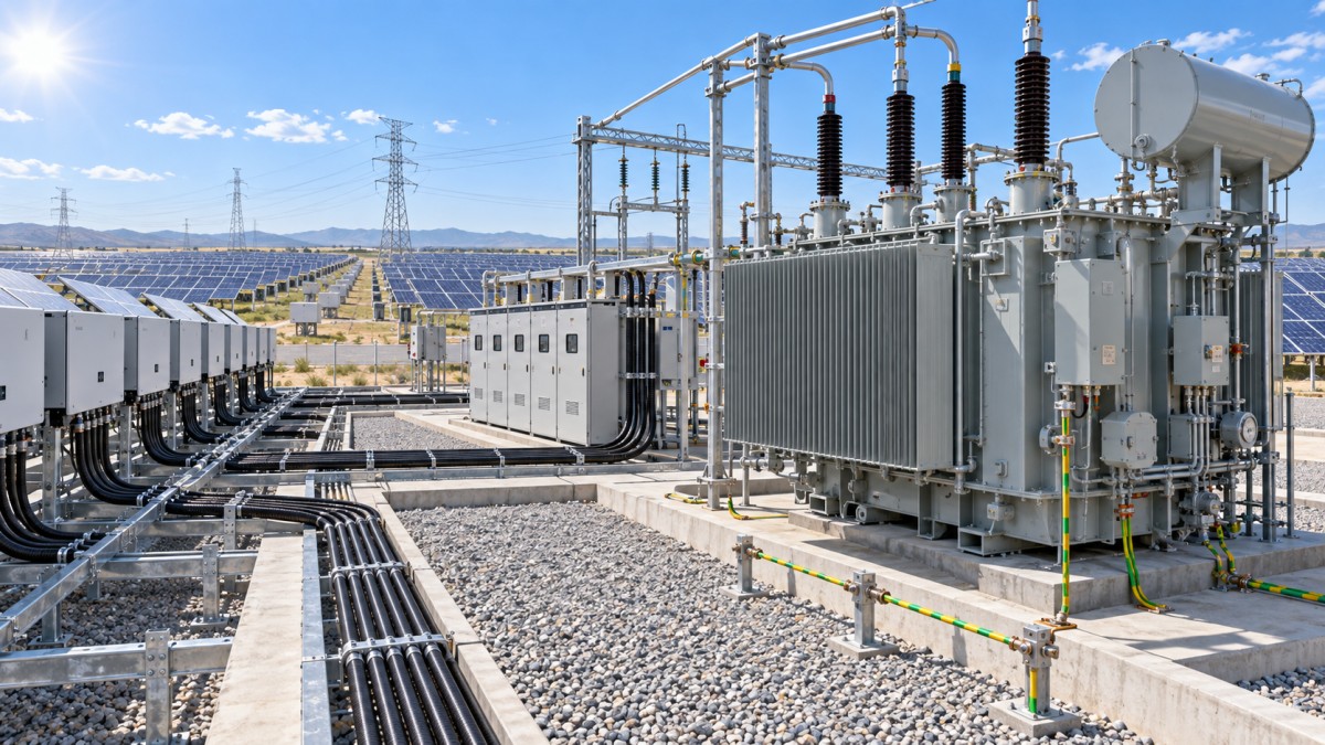
Inverter blocks are often discussed in MW, while transformers are rated in MVA. The conversion depends on the required power factor and the inverter’s capability to deliver or absorb reactive power. A transformer selected only at the plant’s active-power export rating can become the limiting component when the grid operator requires reactive support, voltage regulation, or operation at a power factor below unity.
For example, an inverter block intended to export its full active power while operating at a non-unity power factor may require more apparent-power capacity than its MW rating suggests. The transformer must cover the required continuous apparent power at the applicable ambient conditions. Its rating should also be checked against the inverter’s permitted overload profile, if that profile is expected to be used in operation.
There is no universal rule that the transformer must have a fixed percentage margin over inverter output. A margin may be appropriate, but its value depends on the contracted operating envelope, inverter clipping strategy, local ambient temperature, cooling method, harmonic losses, and whether the transformer is shared by one or several inverter skids. Oversizing without reviewing these factors can add cost and no meaningful operational benefit. Undersizing may force curtailment or accelerate thermal ageing when reactive-power obligations become active.
A sound review separates at least three values:
- The inverter’s maximum AC apparent-power output.
- The plant’s required active and reactive export envelope.
- The transformer’s continuous MVA capability at the specified site temperature, altitude, and cooling condition.
Those values should be compared on the same basis. A nameplate rating at a standard reference temperature does not automatically represent the capacity available at a hot, high-altitude site or inside a constrained inverter station enclosure.
Frequency and Phase Details Are Usually Simple, Until They Are Not
Most utility and commercial solar projects operate at either 50 Hz or 60 Hz, and the transformer must be designed for the system frequency. This should be explicitly stated in procurement documents. A transformer intended for one frequency may not provide the same flux-density margin, loss performance, or thermal capability at the other.
Three-phase compatibility also needs a precise check. The inverter output configuration, transformer winding connection, collector network, and protection scheme must work together. The relevant questions include whether the inverter output is three-wire or requires a neutral reference, whether the transformer will create a grounded neutral on the medium-voltage side, and whether zero-sequence current needs to be blocked or provided with a path.
These decisions are closely tied to the vector group. A delta-wye transformer, for instance, can provide galvanic isolation and influence the passage of zero-sequence components between the low-voltage inverter side and the medium-voltage network. A grounded-wye winding may be necessary to establish the grounding method required by the collector system. The selected vector group also determines phase displacement, which becomes especially important where multiple transformers operate in parallel or where protection relays, metering, and auxiliary transformers are referenced to a common phase convention.
Specifying a familiar vector group without confirming the system grounding and protection design is a common source of late engineering questions. The appropriate connection is project-specific. It should be selected jointly by the inverter engineer, collection-system designer, and protection specialist rather than copied from an earlier project with a different grid interface.
Impedance Must Fit Both Inverter Control and Fault Protection
Transformer impedance is one of the most consequential solar transformer specifications because it affects voltage regulation, fault current, and the behavior seen by the inverter during disturbances. Higher impedance limits fault current, which can help keep switchgear duties within rating. It also causes a larger voltage drop under load and can affect the inverter terminal voltage during high-power or reactive-power operation.
Lower impedance improves voltage regulation but raises available fault current. It may require a higher interrupting rating for downstream equipment and can change relay coordination. Neither direction is automatically better. The selected impedance must be studied with the complete block design: inverter output conductors, low-voltage switchgear, medium-voltage collection cables, other inverter transformers, and the grid source contribution.
Solar inverters behave differently from synchronous generators during faults. Their fault-current contribution is controlled and often limited by inverter protection and grid-support functions. That does not remove the need for a short-circuit study. It makes the study more dependent on accurate inverter behavior data and protection settings. Teams should avoid assuming that conventional generator-transformer rules will produce suitable results without checking the inverter manufacturer’s fault current and ride-through characteristics.
Impedance tolerance also deserves attention where several transformer-inverter blocks are paralleled onto the same collector bus. Material differences in impedance and ratio can create unequal loading. The procurement specification should state the permissible tolerance and identify any grouping requirements for transformers intended to operate in parallel.
Harmonics and Thermal Duty Should Be Addressed Early
Modern grid-tied inverters are designed to control output waveform quality, but their output is still power-electronic in origin. Harmonic current, high-frequency components, switching behavior, and any required filtering can affect transformer losses and heating. The transformer supplier needs the inverter’s harmonic spectrum or the project’s applicable harmonic-duty information, rather than a generic statement that the source is “solar.”
The point is not that every photovoltaic project needs an exotic transformer design. Many do not. The point is that standard loss assumptions may be insufficient if the inverter configuration, filter arrangement, cable layout, or grid requirements produce a material non-sinusoidal duty. Stray losses can rise disproportionately with higher-frequency current components, increasing hot-spot temperature even where RMS current appears acceptable.
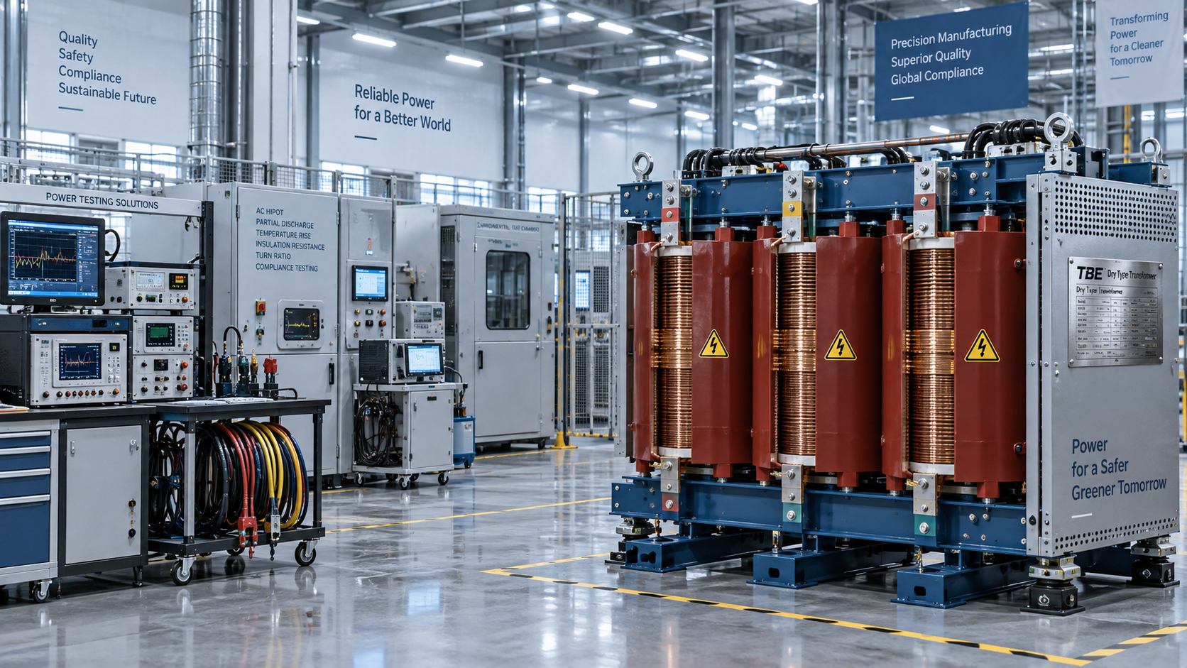
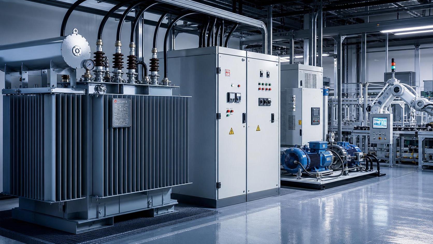
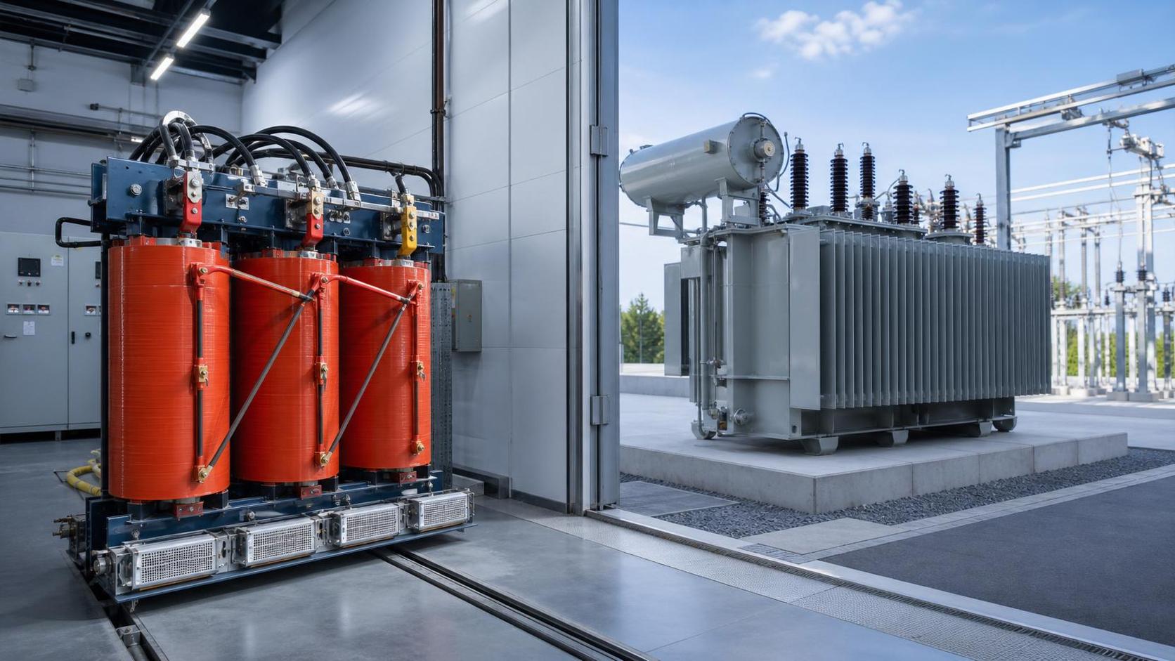
Thermal design must also reflect site conditions. Ambient temperature, solar exposure of outdoor skid equipment, altitude, ventilation, enclosure layout, and cooling medium all affect usable capacity and ageing. An oil-filled transformer and a dry-type transformer have different cooling and installation considerations; either may be appropriate depending on fire requirements, footprint, maintainability, environmental conditions, and local permitting rules.
Procurement documents should state the expected maximum ambient temperature, installation altitude, indoor or outdoor location, cooling class, and any duty that departs from continuous full-load operation. They should also define whether the transformer rating must include allowances for harmonic heating and whether temperature-rise limits are based on the applicable standard and insulation system.
Insulation Level Must Follow the System, Not the Transformer’s MVA Size
Insulation class and basic impulse level are determined by the voltage system and expected overvoltage environment, not by the apparent-power rating alone. The medium-voltage winding requires insulation suitable for the collector system’s nominal voltage, grounding method, switching conditions, cable lengths, surge arresters, and utility requirements. The low-voltage winding also needs a suitable insulation and impulse-withstand design for the inverter-side arrangement.
This issue becomes more important in compact power stations where the transformer sits close to switchgear, cable terminations, and inverter equipment. Cable-fed medium-voltage systems can experience reflected-wave effects and switching transients that deserve coordination between transformer terminals, cable design, surge protection, and switchgear. A transformer meeting a general voltage class is not necessarily sufficient if the project’s insulation-coordination study calls for a different level of protection.
Teams should verify the applicable standards required by the project jurisdiction, utility, lender, or owner. The specification should clearly identify test requirements, insulation levels, dielectric tests, routine tests, and any witness or documentation expectations. Listing a standard without defining the actual electrical ratings and acceptance criteria leaves too much room for inconsistent interpretation during bidding.
Do Not Treat Grounding as an Accessory Decision
The winding connection determines whether and where a neutral point is available. That choice affects ground-fault detection, relay settings, touch-voltage considerations, surge protection, and compliance with the collector-system grounding philosophy. It can also influence the way the inverter responds to unbalanced faults.
A project may require a solidly grounded, resistance-grounded, or isolated medium-voltage system. Each approach imposes different requirements on the transformer neutral, grounding resistor or reactor, protection relays, and cable-screen bonding arrangement. Selecting the transformer before the grounding philosophy is complete can lead to an unsuitable winding connection or an unplanned auxiliary grounding transformer.
Where the inverter manufacturer imposes restrictions on grounding or isolation, those restrictions should be incorporated into the transformer review. The inverter’s internal monitoring and protection functions may depend on a particular AC-side arrangement. This is especially relevant when equipment from different suppliers is combined within a single block.
A Practical Specification Review Before Purchase Order
Before issuing a transformer order, project teams should run a cross-disciplinary check rather than relying on a procurement comparison of MVA and voltage alone. The following items should reconcile across the inverter data sheet, electrical studies, single-line diagram, and transformer vendor offer:
- Rated and allowable inverter AC output voltage, including the intended transformer tap position.
- Maximum continuous and required apparent-power duty, including reactive-power operation and temperature derating.
- System frequency and phase configuration.
- Low- and medium-voltage winding ratings, vector group, phase displacement, and neutral treatment.
- Transformer impedance, tolerance, fault-level impact, and voltage-drop performance.
- Inverter harmonic information, loss evaluation, cooling method, and temperature-rise limits.
- Insulation levels, surge-arrester coordination, and required standards or utility tests.
- Parallel-operation requirements, if more than one transformer feeds the same bus.
- Physical interfaces such as bushings, cable boxes, termination orientation, auxiliaries, monitoring, transport limits, and site access.
The physical interface deserves the same discipline as the electrical one. A transformer can meet every major electrical parameter and still create field modifications if its cable entry, bushing arrangement, footprint, lifting plan, or auxiliary supply does not align with the inverter station and civil layout.
A well-matched transformer gives the inverter a stable electrical environment and gives the project protection scheme predictable behavior. The best procurement decision is therefore not the offer with the nearest nominal voltage and lowest quoted price. It is the one whose electrical duties, insulation design, grounding arrangement, thermal capability, and test scope have been reconciled with the inverter and grid design before manufacturing begins.
Technical Specifications
- What to verify before selecting a transformer manufacturer in the USAAuthor :Electrical Components Editorial Team
- How to choose a cutting machine for stone based on slab thicknessAuthor :Construction Materials Editorial Team
- When are porcelain tiles for outdoor spaces at risk of cracking?Author :Construction Materials Editorial Team
Expert Insights

Chief Security Architect
Dr. Thorne specializes in the intersection of structural engineering and digital resilience. He has advised three G7 governments on industrial infrastructure security.
Core Sector // 01
Security & Safety
- What to verify before selecting a transformer manufacturer in the USAAuthor :Electrical Components Editorial Team

- How to size solar transformer capacity for peak generationAuthor :Electrical Components Editorial Team

- Which solar transformer specifications must match inverter output?Author :Electrical Components Editorial Team

- How do you size a transformer for solar power projects?Author :Electrical Components Editorial Team

- How Transformers Affect Power Stability in Industrial FacilitiesAuthor :Electrical Components Editorial Team

- Dry-Type vs Oil-Filled Transformers: Which Fits Your Project?Author :Electrical Components Editorial Team